Tee

Tee
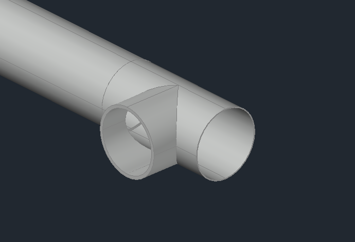
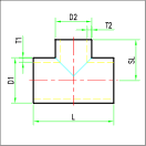
The commands allows to design a tee pipe in 3D and it is represented as a segment of a straight hollow pipe which defines the main axis, characterized by Diameter (D1), Thickness (T1) and Length (L) and a lateral branch with Diameter (D2), Thickness (T2) and Length (SL) drawn from the centre of the tee.
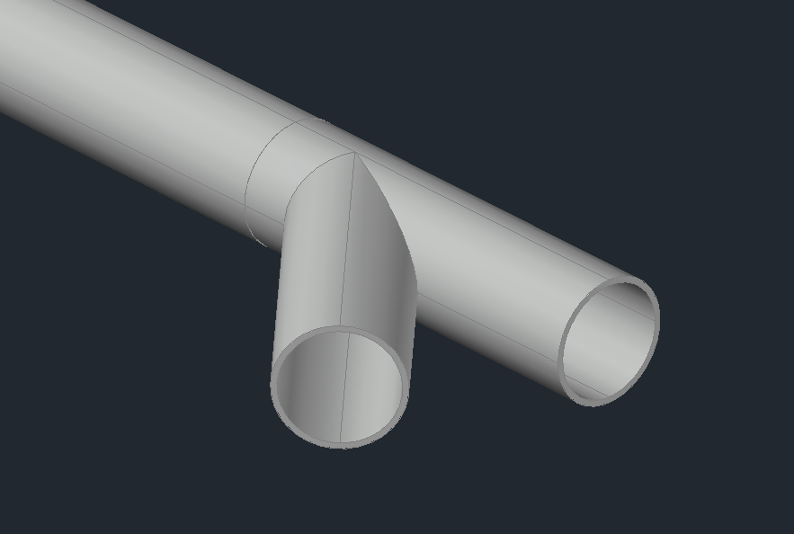
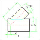
The software also allows to draw Y shaped Tee with the corresponding parameters as in the figure below.
As in reducers, the configuration section shows two reference DN: one for main axis pipe and one for the lateral branch pipe.
In the insertion phase there are the following options:

- Default: Insertion by Connector. The Tee will be inserted with the main axis facing the same way as the selected pipe.
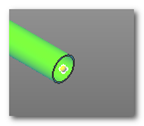
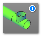
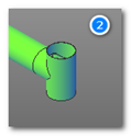
After inserting you'll be asked to Accept or Flip the Tee, in case you wanted the tee to be oriented differently.

Once you've confirmed the position you'll be asked the rotation angle of the tee.
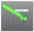
By typing the rotation angle via keyboard or using the protractor the insertion will finish.
- POint: Insertion by point and direction. The direction requested is the direction of the main axis.
- Mid: Creating a branch. In this case you'll be asked to select an existing straight pipe, then the tee will be automatically inserted in the middle of the existing pipe.
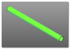
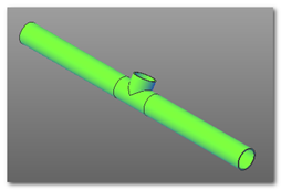
The pre-existing pipe will be cut automatically and two pipes with update details (length) will be generated.
- Fillet: Creating a branch. This solutions is to be chosen when pipes making a t/y shape are already drawn with straight pipes.
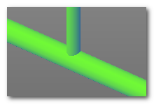
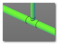
The commands asks you to select the main pipe and the branch one. The tee will be inserted to fit the two pipes, that will adapt with the correct measures.