Components
Components
The software allows to automatically insert the most common components that form piping lines.
Each component shows an insertion dialog used to select the correct typology and measure. The dialogs have common features.
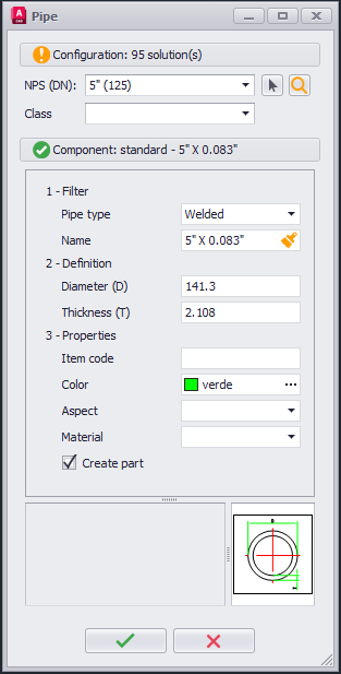
The upper part of the panel defines the "Configuration" based on the DN and current class it shows the number of available library components.
The nominal diameter can be modified choosing it from the standard list or selecting it from the graphical area.
 Graphical Selection: Allows to get the Nominal Diameter from a component already present in the graphical area.
 Components Library: Allows to access the components library.
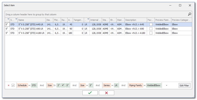
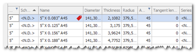
The components library shows a grid with all the available components for the type selected. A filter is automatically activated based on the DN and current class to show only compatible components. This filter can be modified or removed at the user's discretion. All useful fields are available to filter library components.
Selection happens with a double left click on the indicated row or by selecting the row and confirming with the green check button. After confirming the main dialog will update to show the selected component's data. Clicking on the confirm button will start the insertion of the component.ù
The Component section shows the first found configurations.
The icons on the side have a precise meaning:
- Green - Only one solution was found in library.
- Yellow - More than one solution was found in library.
- Red - No solution available in library.
The Component section shows all the component's characteristics divided by typology:
- Filter: Typically the variant or model of the component. It allows you to discriminate the various types of family members present in the database. Each type has a series of dedicated configuration parameters.
- Definition: Typically the geometric data of the component. It contains a series of common parameters for all components: name and description and a series of specific parameters of the components, typically the geometric ones.
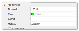
Usually components are selected and loaded from the library without modifying them. The software allows the editing of geometric parameters of the components, it is possible then to design components with custom measurements. - Properties: Component properties are common with all components and are the following:
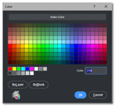
- Color: Allows to select the color to assign to the created solid. The default color is taken from the active line if present. Pressing the selector displays the CAD color selection dialog.
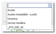
- Aspect: Allows to select the component aspect, intended as "aesthetic material". By pressing the selector the materials present in the drawing are shown. It is therefore necessary to insert the materials to be used beforehand.
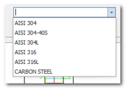
- Material: Allows to select the component's physical material. By pressing the selector the available materials are shown.
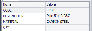
- Item Code: Allows to select the component's code. The piping module uses a coding method coherent with the standard TOP based on coding files located in the Ambient.
By typing a code in the textbox, a code is automatically assigned to the selected component.
The code is assigned based on the Active Component and Material pair, it will be re-proposed in future selections. The created part will have the "Code" attribute automatically compiled.
In the component library, coded components will be highlighted with a tag icon.
 Copy Properties: Allows to select a component from the same family from the drawing to copy its properties.
The Informations section shows the description of the selected parameter and the measurement preview of the selected component.
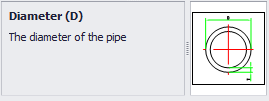
Right section show the preview of the component shape and measures relative to the inserted values.
Left section show informations about the selected field in the above sections.