Parametric Sketches
Parametric Sketches
The TOP Layout is able to load parametric sketches by combining its parametrization with that of the BricsCAD parametric module.
Parametric sketches are useful in all situations where the number of figures to be created would be too high. Parametric figures have limitations, so they are used only in particular cases. Generally only straights and curves are handled in this way.
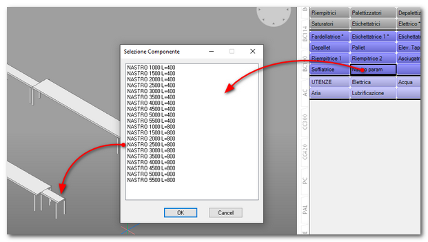
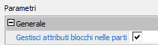
If the (manageblkattribs) option is active, when a 2D or 3D figure is loaded, TOP LAYOUT searches for parametric blocks within the part and applies the parameters defined in the Excel sheet.
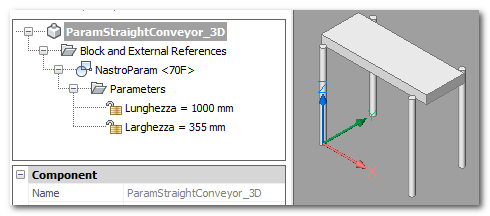
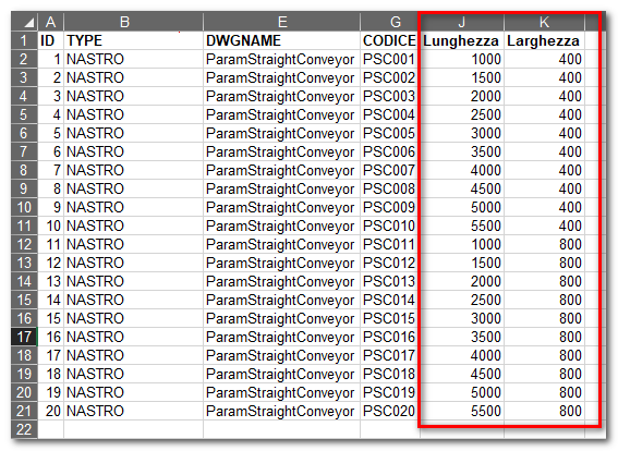
You need to define a library sketch that contains a parametric block and the related tab in the Excel sheet. In the sheet you need to insert and fill in the parameter columns.
|
|
The program only allows you to stretch and move graphic entities. The use is therefore limited to simple figures. There is no possibility of inserting objects parametrically (e.g. the rollers of a roller conveyor or the supports of a transport)
As with native CAD stretch operations, it is important to understand how the command works. The crucial point is the distinction between what is included and what is cut off by selection. All entities cut by the selection polygon will be stretched, while all entities included in the selection polygon will be moved or rotated. For more information, refer to the AutoCAD online help in the section relating to the STRETCH command.
----------------------- STRAIGHTS
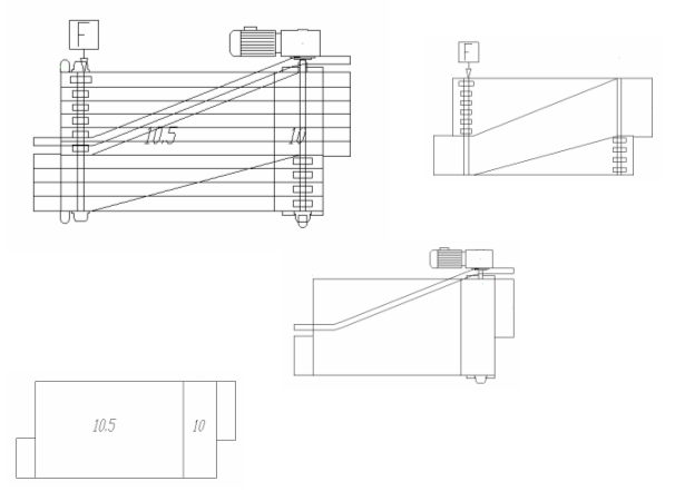
Rectilinear parametric sketches must be created considering length as a parameter. It will therefore be necessary to insert a parametric sketch for each width measurement. Since a "STRETCH" operation is performed on parametric straights, it is necessary to provide the program with the stretching coordinates and direction. To achieve this result we use the mates blocks. There are particular mates to define the stretching area and a mate to define the direction
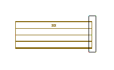
The stretching mates have the name “SNAP_STRETCH_AREAnn” (where it cannot go from 01 to 99) and must be inserted in order as vertices of the stretching polygon. In the example in the figure, the polygon is a simple rectangle so four mates (SNAP_STRETCH_AREA01 - SNAP_STRETCH_AREA04) positioned in the four vertices of the rectangle are sufficient.
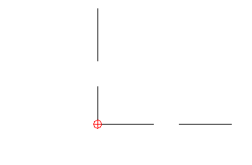
It is very important to respect the order of insertion of the mates otherwise the stretching effect will be incorrect. The direction mate has the name “SNAP_STRETCH_DIR” and can be positioned anywhere in the drawing. In this case the angle at which the mate is inserted is very important. The angle defines the direction of the stretch operation. To facilitate the definition of the stretching direction, the mate has a rather particular shape.
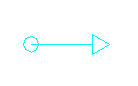
The arrow clearly indicates the direction of stretching.
 Parametric rectilinear figures must be drawn with a base length of 1000 drawing units. This way the software will be able to bring them to the correct size.
----------------------- CURVES
The parametric figures of the curves must be created considering the angle as a parameter. The concept is similar to that of straights but in this case the stretching operation will be angular. For this reason it is important that the curves are drawn as in the figure: with the input (SNAP_IN1) horizontally at 0 degrees and the output (SNAP_OUT1) at 90 degrees. Consequently, the curve must be drawn with a base angle of 90° counterclockwise.
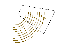
The stretch definition area follows the same rules as the straights. In this case it is not necessary to indicate the direction of the stretching (it is implicit in the direction of rotation of the curve), but it is necessary to define the center of rotation of the stretching. Also in this case there is a special mate: SNAP_STRETCH_CTRROT which must be positioned in the center of rotation.
----------------------- DIFFERENT SKETCHES VISUALIZATION
This method allows you to obtain display filters using TOP categories. It is necessary to aggregate the geometries of the sketches to the desired categories. When the drawing is loaded into TOP, the program automatically sees the categories. In this way it will be possible to turn on and off various components inside the figures transversely to the parts structure.
Please refer to the TOP manual for more information on the categories.