Flange

Flange
The command allows to design flanges in 3D. There are many flange typologies and vary a lot between each other.
Flange typologies:
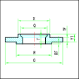
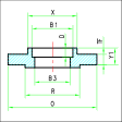
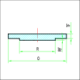
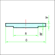
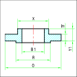
Threaded SocketWelding Blind Lapped Slip-on Welding
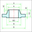
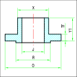
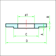
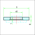
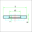
Welding Neck Long Welding Neck Flat Lap Joint Welding Loose Plate for Plate Collar Loose Plate for Weld Collar
The flange command offers the possibility, via an option, to draw the holes. This is a designer's choice based on the details level he wants to give to the drawing.
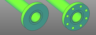
Once selected the typology and the measures of the flange, the insertion phase begins.
The insertion options are the usual one: Connector and Point-Direction. Once the component has been inserted, a request about the fitting position will be shown in case the flange has been inserted the wrong way around, in that case you can flip it by pressing the Flip option, otherwise just click on Accept.

The insertion phase of the flange is a bit different from the standard one. Since the flanges fit together, in the insertion phase it is possible to select both a pipe and another flange. The software automatically detects the position and the direction of the flange based on the selection.
While using the insertion by Connector it is important to select carefully the connector on the correct side of the component.
Flanged Assembly
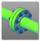
Using the right sequence of the components pipe and flange it is possible, with very little operations, to create a flange assembly.
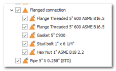
A flange assembly is a coupling characterized by the following components:
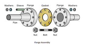
Not all components are mandatory and for some of them a symbolic representation is given.
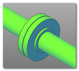
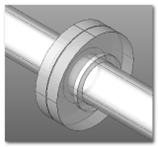
It should be noted that the position of pipes and flanges is performed consistently with the selected flange type. In the case of a Threaded Flange the pipe will be inserted inside the flange, leaving a canonical gap on the abutment face of the flange.

Graphically the is no difference, but a part containing the two flanges and any accessory components like gaskets and bolts will be created.
