Icons of Parts Tree
To make the tree display more intuitive for the user, the latter has various icons available, each of which provides information about the state of the part concerned.
The basic icon set consists of these icons:
 Basic symbol of a part in the parts tree.
 Symbol of the active (current) part. All newly drawn geometries will be automatically aggregated to this part.
 Symbol of a part that is turned off, not visible.
 The part has been cut (see the cut command): it is waiting to be pasted into a new position in the parts tree.
To these are added the Qs Mechanical icons:
 A small 'C' in superscript indicates a part identified by the application as "Commercial".
 A small prohibition symbol in subscript indicates a part set as "Non-editable".
 A small padlock in subscript indicates a part made non-editable by a parent at any level.
If "Data & Drawings" (the PDM developed by Qs Informatica) is also installed, 2 additional buttons will be visible to enable a dedicated display for the state of the parts and of the document and to update these states.
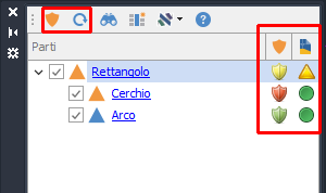
If this display is active, 2 additional columns are shown: one for the state of the part and one for the state of the document. These states are retrieved from the PDM database.
For a detailed guide to the meaning of each icon in these 2 columns, refer to the Data & Drawings manual.
To the left of each part's icon there is a flag that lets the user manage turning the part on\off.
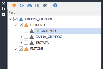
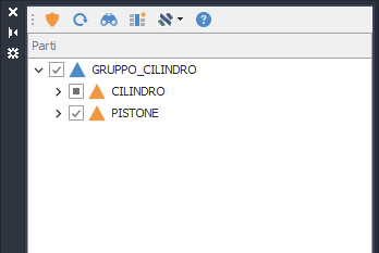
Note: If a part that has children is selected and the tree branch is closed, the effect of turning on/off propagates from the directly affected part to all its subparts.
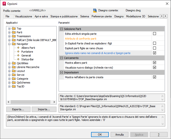
You can force this behavior in any case by changing the setting "Ignore branch state in the Turn On and Turn Off Part commands".