Straight Pipe

Straight Pipe
The command allows to design a straight pipe in 3D and it is represent with a hollow pipe extruded to the required length.
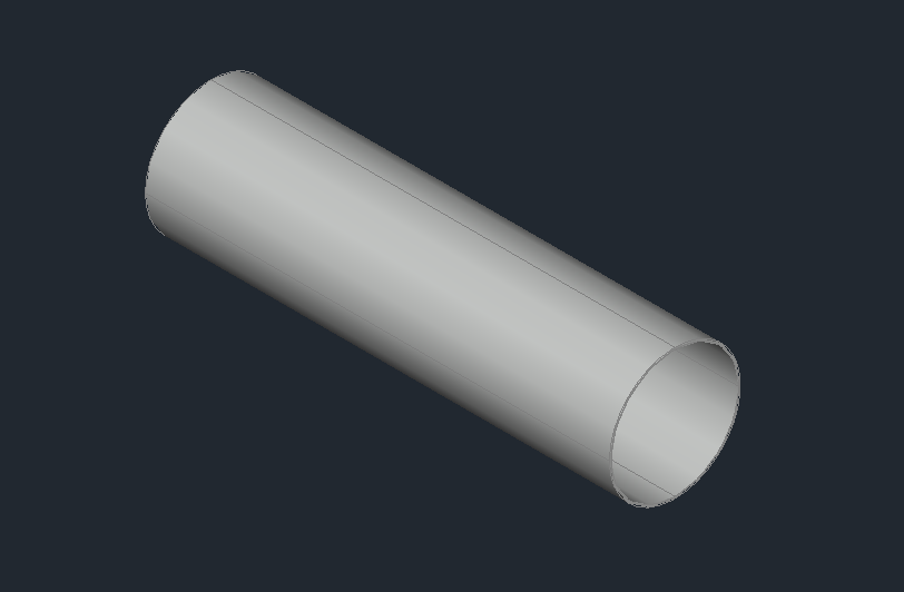
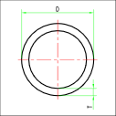
Its main characteristics are Diameter (D) and Thickness (T).
The straight pipe offers the following insertion options:

- Default: Insertion by connector. This is the default insertion typology of the software, with the straight pipe, once selected the connector you are required to insert the length.
![]()
The length value can be inserted manually or by using the other available options
- LImit: You'll be asked to select a point. The length will be equal to distance between the base point of the pipe and the selected point on the pipe axis.
- Copy: You'll be asked to select an existing pipe. The length will be equal to the selected pipe.
- POint: Insertion by pipe and direction.
- TRail: Insertion on a track. The pipe will be drawn following a track and will automatically try to place straights and elbows.
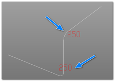
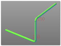
The straight pipe used is the one from the active configuration. The elbow used is the first from the elbows list that satisfy the filter defined from the DN and the current class.
In case no elbow satisfies the request, the software will draw two straight pipes that will require manual processing.

- Flex: Creation of a flexible pipe. It is possible to select any type of 2D or 3D curve as the binary definition for the pipe.
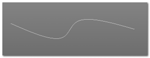
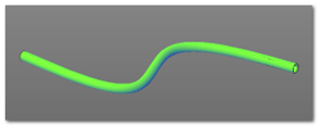
- Mid: Creation of a pipe in the middle of an existing pipe. It is possible to create a branch using the option "mid", using this option you'll be asked to select an existing pipe and the direction of the branch. The starting point of the branch will be automatically defined in the middle of the selected pipe.
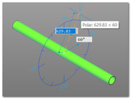
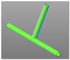
The protractor will be show to simplify the angle selection. Consult Widgets to learn more about the ruler and the protractor.
After the final point has been inserted based on length and angle, the pipe will be generated.
- Jacket: Creation of a Jacket. The software allows the creation of jacketed (concentric) pipes in a very easy way. By selecting the jacket option you'll be asked to select the reference pipe and the software will automatically proceed and create a jacketed pipe. The DN value will determine if the pipe is drawn on the inside or on the outside of the reference pipe.
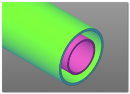
- Routing: Sequential creation of a pipe. The routing mode allows the creation of pipelines composed by straights and curves in a interactive way. To activate routing mode it is necessary to draw at least one straight pipe. After that you'll see the Routing mode on the options list. After activating it the software will change the way it inserts pipes and will show the ruler, waiting for you to select the next point.
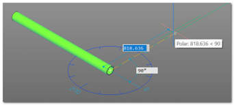
By selecting the next point the software will draw the pipe accordingly to the point chosen, that means it will draw both the elbows and the straight pipes based on DN and current Class selected.
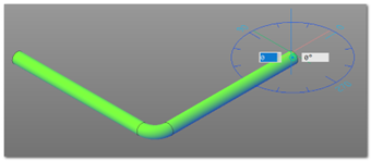
The command keeps waiting for the next point. To change the work surface you can use the appropriate option although for the basic angles (0, 90, 180, 270) it is not strictly necessary.
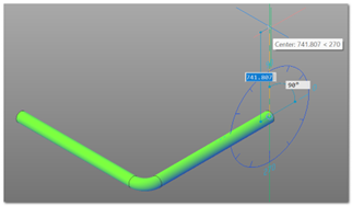
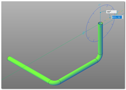
The choice of the curve, as we have said before, is based on the combination of DN and current class. If the angle of the curve is not a value present in the database, the immediately superior curve (in terms of angle) is taken and cut to size. The component registry reports this operation.
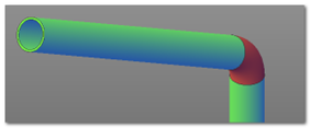

In this example case a 60 degrees elbow is required. A 90 degrees elbow cut at 60 degrees is selected and shown in red to indicate a non-standard component.
- Exit: Stops the command.