Parts Structure
Parts Structure
The schemes module uses the parts structure to save and organize informations in the drawing.
Fluid Part (line)
The structure is composed by a series of "fluid" parts each one composed by "piping" sub-parts. It is not possible to create the fluid part manually, when you'll create the piping part the software will automatically try to find the corresponding fluid part, in case it doesn't find it'll create a new one automatically.
It is possible to create multiple parts for each fluid type in the drawing.
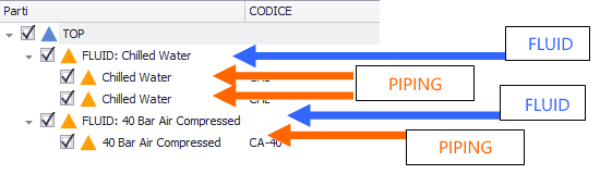
The software always creates piping parts as children of the fluid part. Piping parts though can be organized to have a different hierarchy inside the fluid part, grouping them up on different levels or leaving the all at the same level.
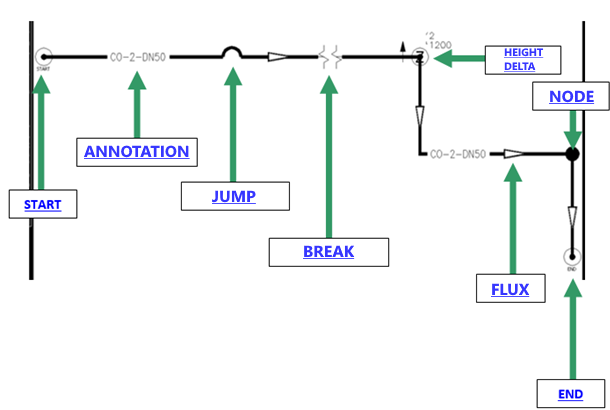
Any geometry attached to the piping part is part of the definition of the pipe. In particular, the polyline represent the pipe.
The pipe part
Each pipe part can be composed by one or more segments of a polyline. The total length of the pipeline is given by the sum of the "straight" length of the polylines. Straight lengths mean that any curved segment of a polyline will be intended as the distance between the start and the end of the arch and not the development of the curve.
A series of special symbols can be inserted by the software in the pipe line to modify the behaviour/aspect.