Connectors
Connectors
The pipes connector inherits its functionalities from 2D and 3D connector but it has specific characteristics for the piping context.
The connector is usually invisible and is show only when necessary.
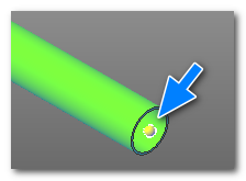
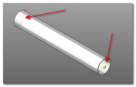
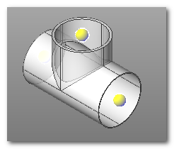
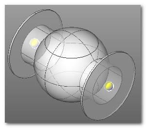
It is represented as small coloured sphere at the ends of pipes. Connectors are automatically created by the software into the library components. Each library component provides one or more connectors, generally one for each possible connection point.
|
|
|
They can be created by the user to enhance the operation of user library components.
Connectors are a fundamental tool when drawing piping lines. They allow automatic snapping of line components when using piping commands and are compatible with the operation part editing commands.
Example
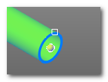
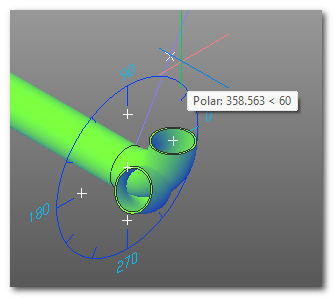
The simplest example is connecting a pipe and an elbow. When inserting the elbow you are automatically prompted to select a connector. Simply select the near connector to obtain automatic connection.
|
|
Manual insertion of connectors

The connectors are created automatically by the software. If necessary, however, they can be inserted manually from the drawing. A typical use case is the preparation of a library component. Let's suppose we want to archive a tank or a pump in the library and want to make the connection points of the components "intelligent". We can use insert connector commands to manually place connectors before saving to the library.
