Concentric Reducer

Concentric Reducer
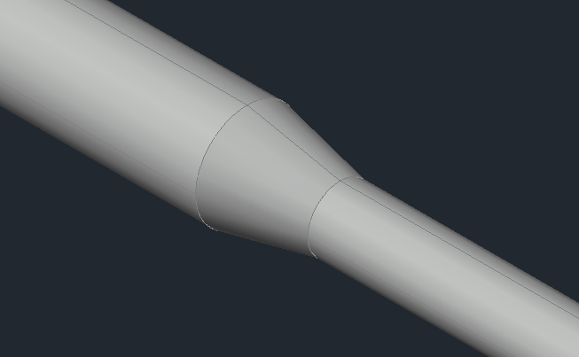
The command allows do design a concentric reducer in 3D, it is represented with a segment of a hollow pipe with variable section, characterized by Start Diameter (D1) and End Diameter (D2) with the relative Thickness (T1 and T2) and Length (L)
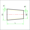
The guidelines of the component dialog are always the same. In this case, since it is a reduction, there are two reference diameters: the inlet and the outlet. The dialogue is initialized with the current DN values and obviously there are no corresponding reductions. By selecting the reference diameters and the class, a search is performed in the component database. If a satisfactory reduction is found it is selected.
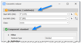
In addition to the selection by DN and class, it is possible to access directly the DB for an advanced research. Once found the correct component we move on to the insertion phase.
The insertion phase provides 2 options
- Default: Insertion by connector.
- POint: Insertion by point and direction.
Once the point and direction has been defined, the component will be inserted.
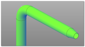
After the insertion you'll be asked if you want to flip the reducer, since it may be position the wrong way around; just click on the flip button. Otherwise if you're satisfied with the placement just click Accept.

In this case the Flip button will produce the following result.
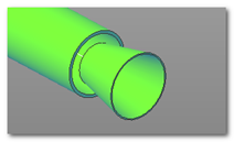
This is obviously not the correct placement ma it could be used in case we want to put a reverse reduction (expansion)
Let's consider the an example of a pipe that goes from 5" to 8". In the database the components are archived as reducers, so we'll have a reduction from 8" to 5"
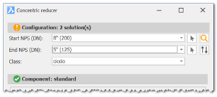
With this config the software will find two solutions. In the insertion phase we flip it and we should have the following result.
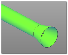
Once the outlet DN has been set, the following pipe will have that DN value as standard to make it easier for the designer.