Component Insertion
Insertion
By pressing the confirm button from the piping menu the software will proceed with the insertion of the component in the drawing area. Each library component has specific different typologies and options. Here there are the most common typologies, leaving the most specific on the pages of the relative component.
- Insertion by connector: This is the default insertion typology of the software. You'll be asked to select a connector to place the component.
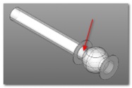
The connector automatically defines position and direction of the component. It is not necessary to select the connect, which is more of a virtual object. It is sufficient to select the solid object near the connector and the software will automatically attach to the nearest connector.
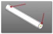
Each piping component has a connector in each connection point. In case of a straight pipe you have two connectors: one in front and one in the back.

The connector selection happens after "touching" the component near the connector.
When you insert a new component, it will be inserted on the selected connector, starting by its base point.

Each time that you'll need to select a connector, every connector existing in drawing will be shown automatically.
In this case you'll be asked the insertion point and then the main axis direction, chosen by indicating a second point on the drawing.
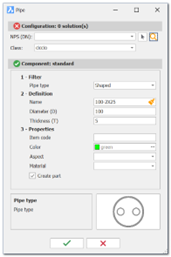
- Customized pipe shapes: The software allows to create custom shaped straight and elbow pipes.

For these components, the shape that defines the pipe must be indicated. The shapes are defined in the Environment folder "piping\shapes".
Each profile must have its own DWG file and preview PNG file. The shape name must be inserted in the database.
For the correct functioning the custom shape must be composed of regions that the software will extrude to the correct length value. The colour of the region is retained as the pipe colour.