Top_Rivetti

Rivets with Lateral and Plan View
Ribbon: Top Mechanical Draw > Mechanical Library > Pin > Rivets
A useful function to draw rivets.
Tabella 15. Rivets Library Table
Blind Rivet A Type |
UNI 9200 |
Blind Rivet B Type |
UNI 9200 |
Opened Threaded Tubular Rivets with Cylindrical Head |
UNI 9201 |
Closed Threaded Tubular Rivets with Cylindrical Head |
UNI 9204 |
Opened Flat Head Countersunk Rivet |
UNI 9202 |
Closed Flat Head Countersunk Rivet |
UNI 9205 |
Opened Plate Edge Head |
UNI 9203 |
Closed Plate Edge Head |
UNI 9206 |
To set the type and the parameters of a rivet, a simple and intuitive dialogue-box is opened with the appropriate commands described hereinafter. As for all standard libraries, it is possible to create a part and insert automatically in the material’s slip the parts used. The code of the rivet’s part is customizable by editing the value in the appropriate space. If the box is left empty, the code will be created automatically.
Click on "Codified Menu" and a dialogue box appears and allows the user to select a specific rivet between all those codified.
- What
- Displays a dialogue-box to set the type of rivet, and its parameters, to insert in the drawing.
- Why
- For the correct drawing of standard section bar, with the abovementioned tables, without necessarily insert all the necessary values to set the object, but selecting in the available list the desired line containing the essential characteristics as the diameter and the height.
- How
- The dialogue-box opened with the command Top_Rivetti is divided in four main sectors.
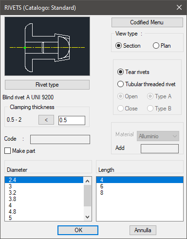
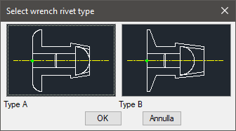
The one on the top left allows to select the type of rivet, just clicking on the icon with the object’s preview, or entering the button Tipo Rivetto (Type of Rivet). It is possible to modify directly on the image the type of rivet and the view necessary to draw the component. Select the button Tipo Rivetto (Type of Rivet) under the image to open a new dialogue-box and select one out of the two types of rivet.
Under this button there is a text line with currently selected object.
Under this button there is a text line with the currently selected object and its view. Once confirmed the type of support to place in the drawing, just insert the object’s layering point and insertion angle.
On the top right side of the main dialogue-box is possible to set as current type of rivet one between Shear Rivets and Open Threaded Tubular Rivets. For the latter, set characteristics as: Opened/Closed and Type A/Type B. In the bottom side there is a box to set the rivet’s clamping length. This value must be set between the maximum and minimum values set and displayed automatically according to the type of rivet set. In the bottom part of the dialogue- box is displayed the list of diameters and relative lengths of the available rivets.
Once confirmed the type of rivet to place in the drawing, just insert the object’s layering point and insertion angle.
(Dialogue...) Insertion Point: Insertion Angle: