Library
This chapter describes the normalized parametric libraries contained in TOP.
First of all, what do we consider by “customized parametric libraries”?
The answer is simple: it is a set of functions to draw a series frequently used UNI-customized mechanical objects (such as Screws, Nuts, Grains, Bearings, etc...), on which parameters (characteristics of the object) the user can act as he wishes, as long as he follows the customization rules. In fact, it is possible to draw a screw of any length or diameter as long as they correspond to the table’s values. In order to verify whether all choices are possible and logical, we will use the application: therefore, the user only needs to select the parameters proposed by the programme, in order to get an object that fits the drawing requirements.
Amongst the possible choices available for each parameter, the less-frequently used are recognizable through the symbol “*”; therefore, it is required not to use them. It is the case for some screws or nuts diameters.
For each element of the library, the designer has, at his disposal, a dialogue box in which all the user’s fundamental parameters, that can be modified, are shown. No logical succession of choices exists, which means that the user is completely free to navigate inside the dialogue box.
Except the holes, each element of the library can turn into a part whether this option is activated or not. For some elements, it will be possible to create more parts: e.g. for the screws, it could be possible to draw a screw with more than one washers and one nut. In such a case, we will create the screw’s part, the washer’s part, and one for the nut. For each single part are set the enhancements Name, Code, Denomination, and, if necessary, the Material and the insertion point of the object. The part’s enhancement Code is linked to a text-box in the dialogue. If this box is left empty, the code will be created automatically; if the box is modified, the code will be customized with the inserted string.
On each created part, we find all the available functions that are described in Chapter “ The Parts”.
Each typology of parametric libraries gives the user one main dialogue and one for the codified objects, distinguished according to the user’s operations. On one hand, the main dialogue allows the user to select the parameters of the drawing, which are chosen amongst all the unified parameters proposed by the application. On the other hand, the codified dialogue allows to select the detail between, and only between, the parameters that were previously codified. On the following page, we describe both types of dialogue in the specific case of screws, even though the structure needs to be considered identical for all types of parametric libraries.
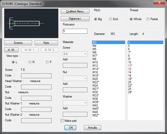
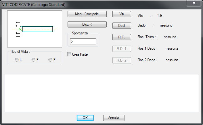
Press the Menu Codify to move from the main dialogue to the codified one:
The pitch type used in the drawings is Big, even if you select a thin pitch in the dialogue box: such a choice has been made only for aesthetic reasons. In fact the pitch in the maintenance of the object will result thin
In Codify menu, the code index is in alphabetical order. The width of the threading is defined by multiplying the pitch by an adequate constant set for the ISO threading with a triangular profile: h3= 0.61343 P.
The depth of the tapped blind holes can be measured in two ways: from the laying point to the hedge of the top (Total) or from the laying point at the hedge of the thread (Partial).
To modify the depth of the holes, enter the command Top_TipoLungFr, described in paragraph 4.3. Customization Commands.
The nib of the untapped part in the tapped blind holes is defined in the UNI 5710 table, after having calculated the pitch.
Press OK to insert in the dialogue the selected component in the active library.
When you close the main dialogue box, the user cannot immediately lay the object because a last dialogue box is displayed, as illustrated hereunder.
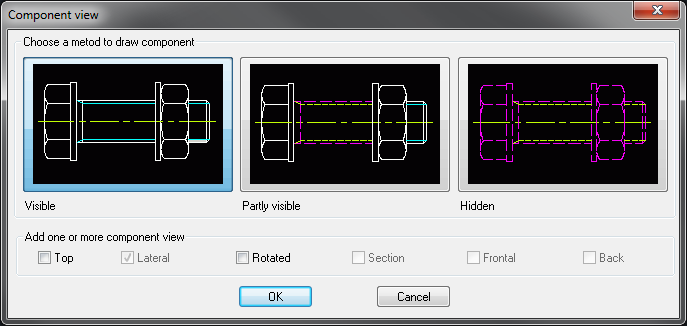
This dialogue box allows the user to select the different component view modes inside the drawing. Indeed, it is possible to choose to display entirely or not a part, as if it would be covered by another component. For the screws, it is also possible to choose the option "Partially visible", which draws the visible part, but the central tapped part is to be found between the non visible head and nut.
Another important characteristic of this dialogue box is that the user can decide to draw, at the same time, the previously-selected component in different view modes, in order to considerably accelerate the work.
In order to get an example, we refer, once again, to the dialogue box of the screws: the user can draw a screw with the lateral view and, at the same time, in plan view by selecting the dedicated toggle.
Of course, the toggles, referring to the views that were not planned for this type of components, are deactivated. This important function is available for all the application’s libraries, and therefore will be described in this introduction only.
|
Nota |
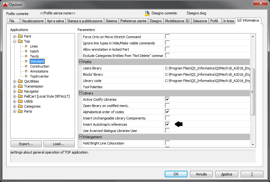
For all the components of the library, the symmetry axis are drawn with the linetype MIXED THIN, set through the dedicated command, and they are always drawn except when other axis are overlapped. In the library's dialogs (Drillings, Screws, self-tapping screw, Nuts, Rosettes, Sections, Hollow profiles, Bars, Bearing), next to the name in the upper left, is specified the catalog from which components were taken. The design of the AutoSnap's block is optional and can be disabled by setting the appropriate variable in the options. Opzioni > Top > Standard > Library > Inserisci Riferimento di AutoSnap
|
![[Nota]](lib/imgnote69.png)