Top_Spine

Draw Pins
Ribbon: Top Mechanical Draw > Mechanical Library > Pins
With TOP the user disposes of a series of standard pins that can be managed using a dedicated dialogue box.. The only important parameter to draw a pin the user can modify is the diameter.
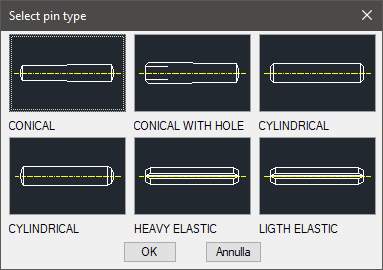
Tabella 7. Pin Standards Table
Taper |
UNI 7283 |
Taper with threaded hole |
UNI 7284 |
Parallel dowel or link pin |
UNI 1707 |
Hardened parallel dowel |
UNI 6364 |
Elastic Heavy |
UNI 6873-71 |
Elastic Light |
UNI 6874-71 |
- What
- Draws most common pins with lateral or plan view.
- Why
- To insert in a drawing a pin conform to UNI standards, and possibility to create a part and manage the element in the material’s BOM.
- How
- To manage the pins, the designer can use a simple and intuitive dialogue-box. In the dialogue-box there is: an image which displays the pin in the selected view; a list of the available diameters; a list on the available lengths; a button to select the type; a text-line to display the description of the selected pin; and a button to create the part.
Click on the right side of the image to change the type of pin; click on the left side to change the view (from lateral to plan, or from plan to lateral).
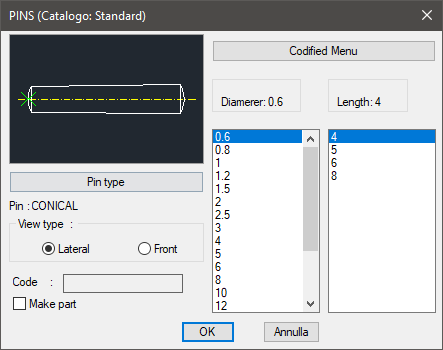
To change the type of pin, press the button "Pins…" to display another dialogue-box and select one of the available pins.
The diameter and the length are available in two lists containing all the values of the selected type of pin.
In the dialogue-box there is a button which can create the pin's part. The code of the created part is customizable by editing the value in the appropriate space. If this space remains empty, the code will be created automatically. Click on Codify Menu and a dialogue box appears and allows the user to select a specific pin between all those codified. Once selected the pin, insert the layering point and the insertion angle.
Command: Top_Spine <ENTER> (Dialogue...)
Insertion Point: Insertion Angle <0>: <ENTER>