Top_Ruote_Den

Cylindrical Gear Wheels
Menu: Top > Library > Gears > Cylindrical Gear Wheels
A useful function to draw cylindrical gear wheels. To quickly set the type of gear wheel, its mode and the other parameters, a simple and intuitive dialogue-box is opened with the appropriate commands described hereinafter.
As for all standard libraries, it is possible to create a part and insert automatically in the material’s slip the parts used. The code of the gear wheel’s part is customizable by editing the value in the appropriate space.
If the box is left empty, the code will be created automatically. Click on "Codified Menu" and a dialogue box appears and allows the user to select a specific gear wheel between all those codified.
- What
- Displays a dialogue-box to set the type and the specific parameters of a gear wheel to insert in the drawing.
- Why
- For the correct drawing of gear wheels, with standard dimensions, by selecting in the appropriate list the type, the mode, and the desired line with the essential characteristics.
- How
- The dialogue-box opened with the command Top_Ruote_Den is divided in four main sectors, as described in the image below.
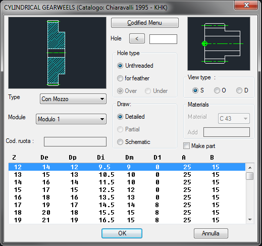
The first section on the left displays the preview of the gear wheel. Click on it to modify the view and visualize real-time the graphic changes.
Under the graphic representation are displayed two pup-up list to select the type of gear wheel and the mode, which determines the dimensions of the teeth.
In the first section is also possible to add or consult the code of the selected part, which will be added to the part’s enhancements.
In the central sector, besides the button "Codified Menu", is possible to modify the central hole of the gear wheel by inserting the value with the keyboard, or selecting two points on the screen. The value of the hole must be between the “Dm” and “D1” values.
Thus, select the type of hole and the drawing mode, as described for the pulleys and the sprockets.
On the right sector is displayed an image to insert the most appropriate layering point of the gear wheel.
Under this image is possible to set the view – Plan, Front or Rear – of the gear wheel.
In this sector is also possible to create a part with the dedicated toggle, thus add and select the material necessary for the component to draw.
Under these three sections is displayed the list of the component’s graphic parameters, easy to consult and select.
Once confirmed the object to place in the drawing, just insert the object’s layering point and insertion angle.
Example 151. Draw Cylindrical Gear Wheels
(Dialogue...) Insertion Point: Insertion Angle: