Top_PullTrap

Trapezoidal Pulleys
Menu: Top > Library > Gears > Trapezoidal Pulleys
A convenient feature for the drawing of trapezoidal pulleys and related belts is made available to the user.
The types of pulleys available are four:
Tabella 21. Trapezoidal Pulley Library Table
Light Alloy Step V-belt Pulleys. |
Z - SPZ - 3V \ A - SPA \ B - SPB - 5V |
Cast Iron Monobloc V-belt Pulleys. |
A - SPA \ B - SPB - 5V \ C |
Light Alloy MonoblocV-belt Pulleys. |
Z - SPZ - 3V \ A - SPA \ B - SPB - 5V |
PMA V-belt Pulleys for taper bushing. |
Z - SPZ - 3V \ A - SPA \ B - SPB - 5V \ C - SPC |
In order to allow the user to quickly select the type of pulley, its execution and the other parameters it is launched a simple and intuitive dialogue box allowing the end user to freely move with the commands that will be subsequently described.
As with all other normalized libraries you can create a part in order to have automatically added the pieces used to the bill of materials. The part number related to the pulley can be customized at will by editing its value in the specific space. If this value is not entered, the code will be created automatically.
Activating the Encoding Menu button appears a dialogue box that allows user to select a particular pulley among all (and only) those encoded.
- What
- Shows a dialogue box where you can determine the type and the specific parameters of a pulley to enter in the drawing in a precise and functional way.
- Why
- The command is used for the correct pulleys drawing with dimensioning according to the law indicating the type, the profile and the number of grooves besides the desired line containing the essential characteristics in the specific selection list of the dialogue.
- How
- The dialogue box referring to the command Top_PullTrap is divided into four main areas as it can easily be seen from the figure below.
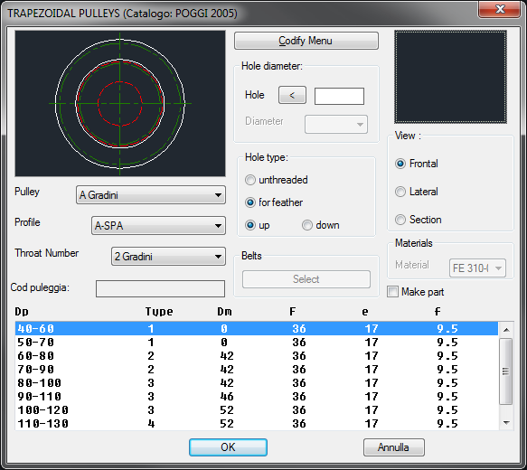
On the top left there is the figure that shows a preview of the piece selected by the user through the various controls. By clicking on this image you can change the various views of the pulley. Still in the same section, below the image, there are three drop-down menus that allow you to select the type of pulley, the profile of the grooves and finally the number of grooves. Even whithin the first column of the dialogue we find immediately below the edit-box where the user can enter the code of the pulley.
Besides the Encoding Menu button already described, within the central section, we find the part reserved to changing of the central hole of the pulley whose size can be inserted according to different modalities depending on the type of pulley. As a general rule, for the most part of the pulleys, the diameter of the central hole can be entered from keyboard or selected to screen through the selection of two points into the special edit box of the first line. In any case the measurement so obtained must be always between Dm and d. For pulleys with clamping bush this edit box is disabled, while the underlying drop-menu is enabled, from which you can select a specific hole diameter from those available for the bush that is mounted from that particular pulley. A pulley inserted with this type of bush has always a hole for tongue, as bushes are already produced in this way. If you select a pulley that has not a bush the section below is also made available, from where it is possible to select the type of hole that you want to make. So as in other libraries here you also have the opportunity to decide if you want a smooth hole or for tongue and the place where to make the fissure for this.
In the bottom of this column, the last control allows us to eventually select the belt that must be mounted on this pulley. By clicking on "Select" button then you'll see the dialogue below.
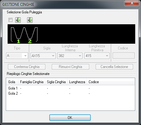
In the upper part, depending on the pulley selected in the previous dialogue, you will be shown a schematization of the available grooves. In the example we have a pulley with 5 grooves where it will be then possible to mount up to a maximum of 5 belts. For each pulley groove it is available a special arrow-shaped little key that allows us to select it. When a groove is selected inside it, a red belt will appear in section in oder to highlight which grooves you are going to act on. It is also enabled a series of controls from which it is possible to select the desired type of belt and codify it. Selecting more grooves it is possible to mount or remove more belts simultaneously. If you want to select all pulley grooves it is advisable to act on the check in the upper left corner, which acts as "Select All". As we said below the schematization of the pulley it is available a set of controls that allow us to select the belt that best satisfies our needs. The first drop-down menu to the left allows you to select the type of belt. In order to facilitate the task to the user, this drop-down menu only shows the belt types compatible with the pulley that you are configuring. Instead, the following three drop-down menus go along, that is to say that all three are necessary to identify the belt to be mounted according to three different parameters, but unique anyway. Then you can select the belt both through its abbreviation and its internal or original length. The last line check allows us to assign a code to the component, similarly to what happens for every TOP library. The line of buttons below acts on the grooves selection made previously. By clicking on "Confirm Belt" the belt selection, previously made in the grooves selected, will be finalized. This will update the summary in the underlying box, while the summary figure above the grooves will be filled by the drawing of the belt selected in section. By clicking on the second button "Remove Belt" any belts already selected will be removed from the selected grooves. The last button of the line, "Erase Selection", has the function to deselect all the previously selected grooves. As already mentioned, the lower part of the dialogue fulfil the summary function of the belts selected. In fact the various pulley grooves appear in ascending order and next to each one there are the data and the code of the belt eventually selected. When we have completed this selection phase, confirming the choices made, we will return to the previous selection screen of the pulley. Let’s complete the analysis considering the third column.
In the right section the user can select the point in which to place the pulley in the drawing. At the bottom of this figure you are given the possibility to choose the view of the pulley that can be Front, Side or Section. Always within this part there are the materials selection box useful for the part creation, in addition to the control in order to indicate its creation.
Below these three sections, user can select in the specific list the parameters useful for the pulley drawing. Once you have confirmed the object to be placed in the drawing you just must indicate the installation point and the angle of insertion of the object.
Depending on the selection you made earlier in the belts dialogue will be created different parts for the pulley and every single belt.
Example 150. Draw Trapezoidal Pulley
(Dialogue...) Insertion Point: Insertion Angle: