Tee

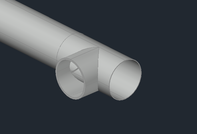
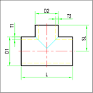
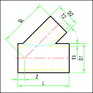
The command allows you to draw a tee in 3D, which is represented as a straight hollow tube defining the main axis, characterized by Diameter (D1), Thickness (T1), and Length (L), along with a lateral branch having Diameter (D2), Thickness (T2), and a Length (SL) defined from the center of the tee.
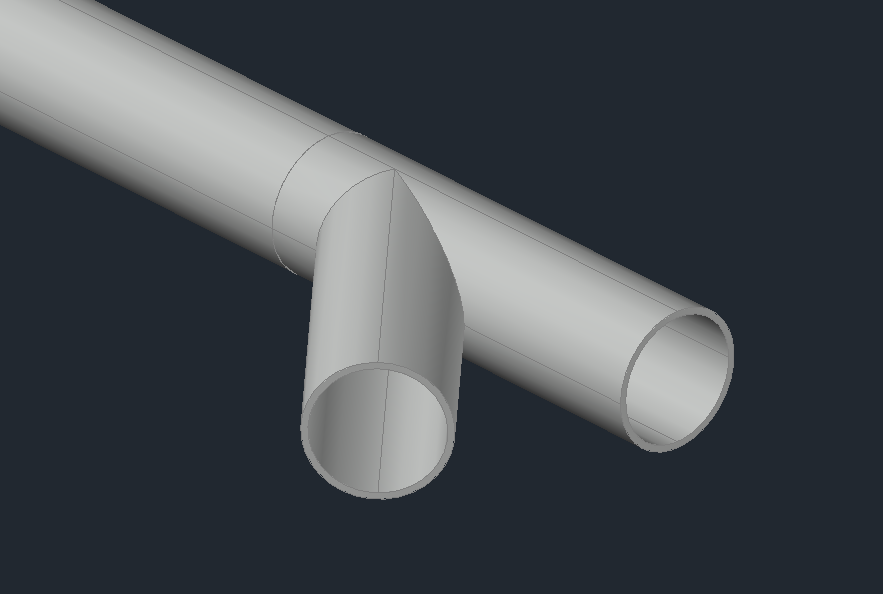
the software consent to draw Y shaped tee.
As with reductions, the configuration section displays the two reference DN: the one for the pipe on the main axis and the one for the pipe on the secondary axis.
During insertion, the following options are available:
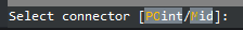
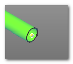
Default: Insertion by connector. The Tee will be inserted with the main axis aligned with the selected pipe axis, and the connectors will be automatically attached.
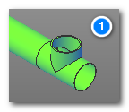
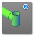
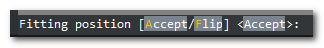
At this point, the option to accept or change the component's placement is shown. If you want to connect the component to the secondary axis, select the "Flip" option.
Once the correct placement is defined, the component's rotation angle is requested.