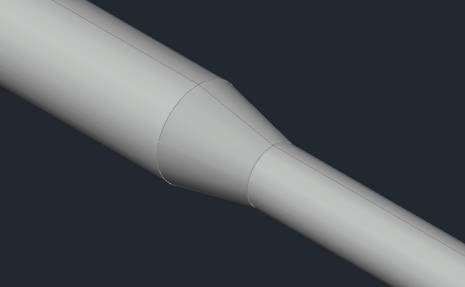
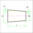
Concentric reduction

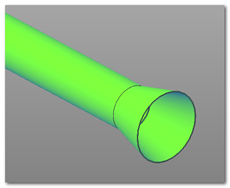
The command allows you to draw a concentric reducer in 3D, represented by a segment of hollow pipe with a variable cross-section, characterized by the input (D1) and output (D2) diameters, with the corresponding thicknesses (T1 and T2), and a Length (L).
ChatGPT ha detto:
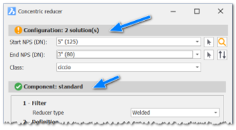
The configuration dialog guidelines for the component are always the same. In this case, since it's a reducer, the reference diameters are two: the inlet diameter and the outlet diameter. The dialog is initialized with the current DN values, and naturally, no corresponding reducers exist yet. By selecting the reference diameters and class, the system performs a search in the component database. If a suitable reducer is found, it is selected.
In addition to the selection by DN and class, it is also possible to access the database directly for an advanced search. Once the correct component is identified, the next step is the insertion phase. The insertion modes are:
- Default: Insertion via connector.
- Point: Insertion by point and direction.
Once the point and direction are defined, the component is inserted.
Some options are displayed if the component is not inserted in the required mode. These options allow the user to adjust or correct the placement of the component to ensure it aligns with the intended design.
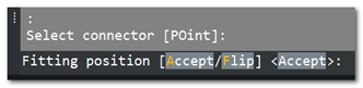
Accept: Confirms the current configuration, finalizing the placement of the component as it is.
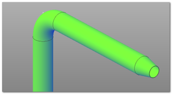
Flip: Reattaches the component to the next connector. This option would produce the following result:
The component would be flipped, aligning with the new connector orientation, ensuring the correct direction and positioning in the system design.
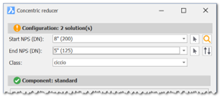
With this configuration, we will find two solutions. During the insertion phase, using the Flip option, we can achieve the desired result.
Once the outlet DN is set, this value is kept as the current DN to facilitate the continuation of the piping line construction.