Bulloning

The command allows you to draw a bolted connection in 3D. It supports bolting for flanges. For the loading of individual bolts, refer to the QSiLibrary.
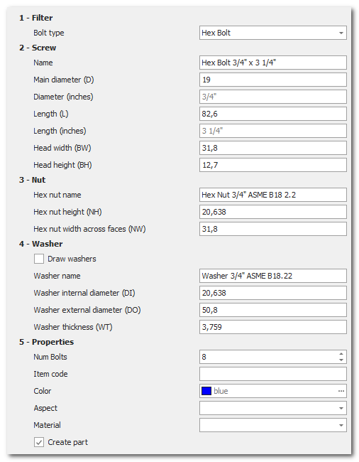
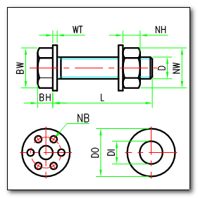
The bolting parameters include several settings to define each individual component.
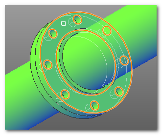
To perform the bolting of a flange connection, you need to select one of the flanges so that the software can read its characteristics. This operation is done by selecting the flange in the graphical area.
The software uses predefined bolting tables for each type of flange. Once the selection is made, you need to define the type of bolting:
- Hex bolt bolting (hex bolt)
- Stud bolt bolting (stud bolt)
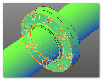
The software then offers the option to indicate whether to draw the washers or not. After defining the configuration, you can proceed with the drawing. The bolting is carried out by selecting the two outer faces (not in contact) of the flanges. You begin by selecting the first face:
![]()
ned it finishes with the selection of the opposite face
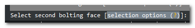
Once the selection is complete, the software will proceed to create the bolting for the flange.
|
|
|
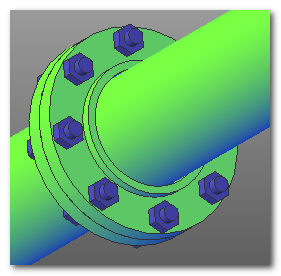
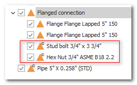
Based on the selected options, the software will create the parts for all the bolt components: screws, nuts, and washers. The module generates a single part with the correct quantity of items in the bill of materials (BOM).