Topx_LoadPrt

Menu: Top3D > Carica Parte...
- What
Loads an external component (DWG) defined for parts and arrange it in the current project.
- Why
- The command TOPX_LOADPRT permits to do a “load 3D part”. The command has been studied specifically for loading a 3D model and arrange it correctly.
- How
- Launched the command it asks the positioning in the current project.
- it has the same features as a normal "load part" except for the request of the scale factor and it offers the following extra features
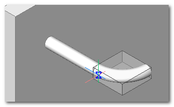
Identification of the support plane
The command recognise automatically the support plane of the model when changing the position of the mouse cursor. TOP identify the underneath geometry and determine its reference plane automatically adapting the UCS as outcome.
Once defined the support plane the SHIFT key can be pressed to block the support plane. This way the plane will remain defined even when changing the underneath geometries.
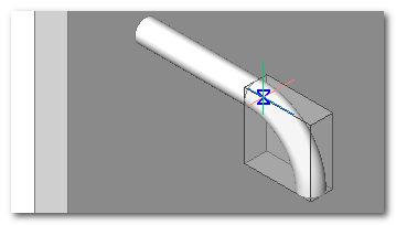
Automatic definition of ____
In the part insertion phase it automatically draws the external ___ in translucence. This helps in the positioning of the part inside the drawing.
Variable positioning point
During the insertion phase the reference point can be modified by pressing the TAB key. Usually the following points are considered: point of part insertion, inferior points external ___.
Orientation flip
During the insertion phase it is possible to modify the normal (Z axis) of the component by pressing CTRL key.
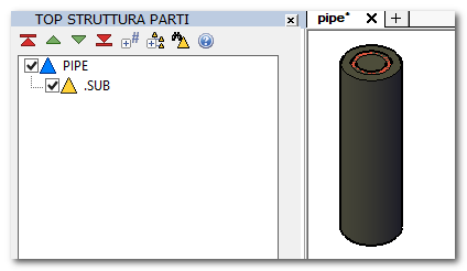
Automatic subtraction
The loaded parts can be arranged to do an emptying operation on the destination part. This can be used to make a “location” for the loaded part; such as the transition hole of a pipe or a bolt otherwise at the foundation for a machinery base.
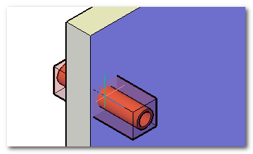
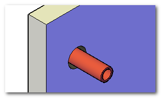
To do the automatic subtraction it's enough to make a sub-part named “.sub” inside the part that has to be inserted. 3D solids defined inside this part will be used to make a boolean operation in the destination drawing.
To identify the solid ___ will be used the ____ of the subtraction solids.
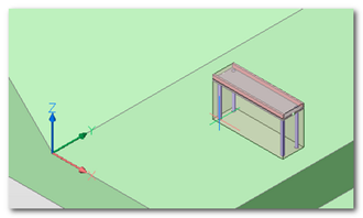
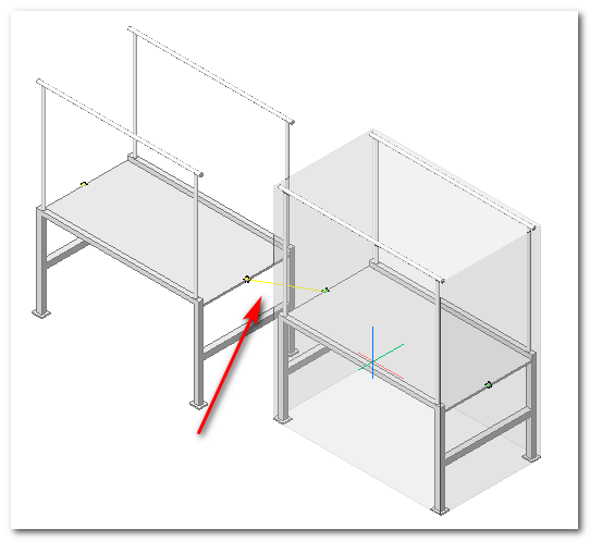
Automatic connection
The 3D loading mechanism support the part connectors. In loading phase the components connectors are highlighted by a coloured sphere to simplify the hooking.
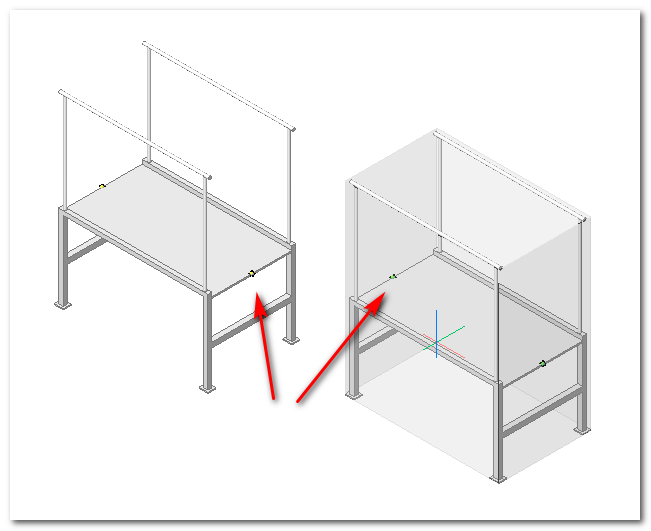
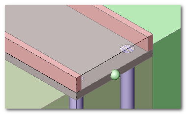
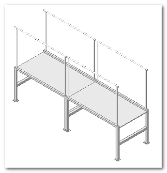
When two connectors are approaching an elastic line that shows the possible hooking is highlighted. Drawing near the components the conclusive hooking effect take place.
Once the components are hooked they get deleted from the drawing.
In the components insertion phase it is possible to steer the inserted part around the insertion axis by pressing CTRL key. A 90° rotation is done after every key pressing.