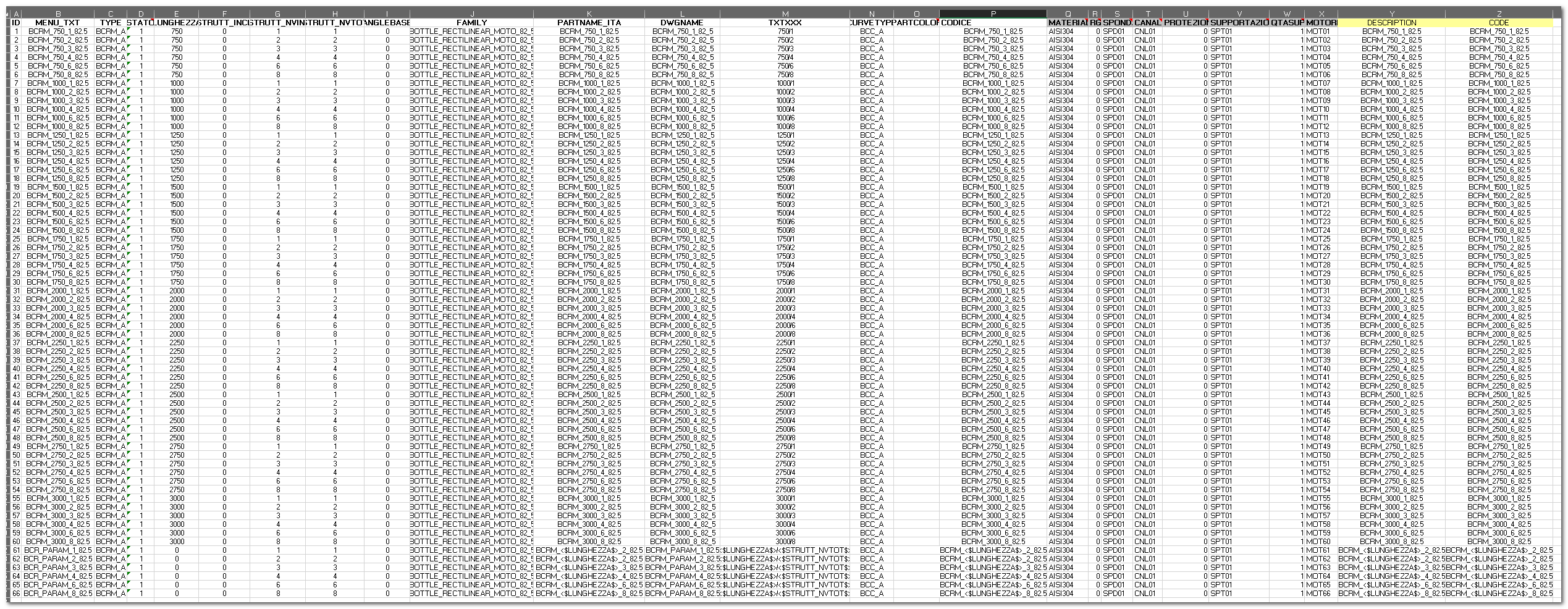
Fields of the components sheet
Each family has a component sheet (defined by the name set in DESCRIPTORS_DICT/TAB_DESC) that defines the behaviour of the single family components. This sheet is typically very big and allows to determine with extreme precision the anagraphical behaviour of each component. Do not let the dimensions of the table scare you, since most of the values are often very similar and can also be copied with the standard excel drag function.

In this sheet we define the behaviour of each component inserted by console. The console deduces from this tab the component to insert by inferring the path from the "FAMILY" and "DWGNAME" fields.
Standard Fields
Each family sheet is composed by a series of standard fields and some other component specific fields. The components sheets must have a series of standard columns, these are necessary for the software to work correctly:
ID, STATO, TYPE, CURVETYPE, FAMILY, DWGNAME, PARTNAME_ITA, MENU_TXT, CODICE, ANGLEBASE, STRUTT_INCL, STRUTT_NVIN1, STRUTT_NVIN2, STRUTT_NVUS1, STRUTT_NVUS2, STRUTT_NVTOT, STRUTT_ANG, STRUTT_RAGM, APP_RETT, RMED, LUNGHEZZA, PARTCOLOR, TXTXXX.
The are certain known limitations of using Excel as a Database:
 Additional columns can be inserted, for a maximum of a 256. In the case of very large databases it is recommended to integrate some tables or separate the database based on the type of transport. The program is already prepared for the separation of air, bottles and packaging transport.
 The table reading module interprets the data type of the column by analyzing the first 8 rows. Evaluating the data content of the first 8 lines determines the data type (Numeric, String, ....) Storing TOP attributes.
The header content is used as the corresponding TOP attribute value. All the columns present in the sheet are saved as TOP attributes. When the program inserts a sketch it executes a query on the database sheet. All the columns of the sheet will be saved as attributes in the part. That means that adding an attribute to the sketch is as simple as adding a column to the database table and type the value. The columns of which the name start with an underscore "_" are not saved as TOP attributes. Pay attention to not edit the standard fields names. Fr example the attribute "_MATERIALE" won't be saved as a part attribute. These attributes can be used for operations inside the worksheet without influencing the values of part attributes.
In the components sheet calculations, formulas and VBA macros are all allowed.
The TOP LAYOUT Module automatically manages the insertion of parametric sketches (variable length). The parametric sketches need particular rows in the excel sheet. The key field (the parameter) must have value = 0 (zero) for it to be recognised as a parametric sketch. For the straights the LUNGHEZZA field must be 0, for curves STRUTT_ANG must be 0.
Some field (columns) do not have any useful meaning for parametric sketches, some work differently. In particular PARTNAME_ITA and TXTXXX can contain variables which represent the values of the attributes contained between square brackets <$$>. This way if we want a parametric sketch that shows its real length in the name we can set the PARTNAME_ITA as "BCR_<$LUNGHEZZA$>_8_82_5". The software will automatically replace the <$LUNGHEZZA$> with the value in the length value. If we use curly brackets the software will recognize it as LUA code and will execute it. The variable will be replaced by the LUA code snippet. In the same way we can work on the TXTXXX field. For example the value <$LUNGHEZZA%>/<$STRUTT_NVTOT$> will become 3150/4 if the values of the attributes LUNGHEZZA and STRUTT_NVTOT will be respectively 3000 and 4. Generally speaking, in each column we can insert variable (defined via the part attributes) by including them between square brackets.
For some components it might be necessary to request a confirmation by the user by showing a default value. This can be obtained by inserting the <?> tag inside the cell that has to contain the attribute value (1)
