Top_Cavi

Hollow Sections
Ribbon: Top Mechanical Draw > Mechanical Library > Semifinisched > Hollow Sections
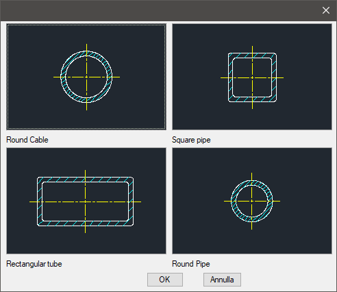
A useful function to draw standard hollow sections. The types of hollow sections are: Round, Square, Rectangular and Tube.
To set the type and the parameters of a hollow section, a simple dialogue-box is opened with the appropriate commands described hereinafter.
As for all standard libraries, it is possible to create a part and insert automatically in the material’s slip the parts used. The code of the section bar’s part is customizable, as for the previous sections, by editing the value in the appropriate space of the main dialogue-box called "Code".
If the box is left empty, the code will be created automatically.
- What
- A dialogue-box to draw with precision the object is displayed to set the type of hollow section, it’s view and its parameters.
- Why
- For the correct drawing of standard section bar, with the abovementioned tables, without necessarily insert all the necessary values to set the object, but selecting in the available list the desired line containing the essential characteristics as the width, the height, etc…
- How
- The dialogue-box opened with the command Top_Cavi is divided in four main sectors:
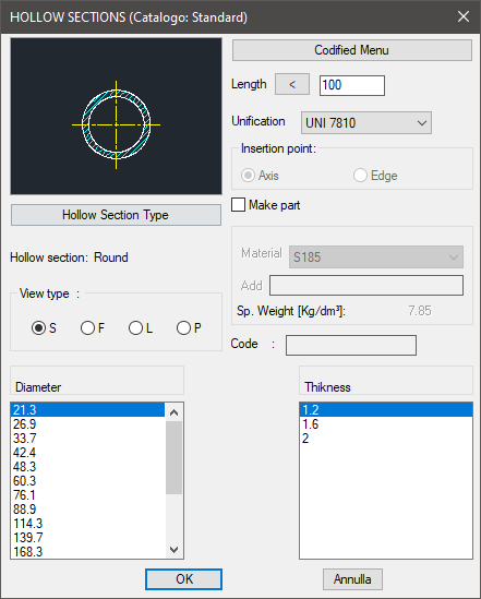
The one on the top left allows to select the type of hollow section, just clicking on the icon with the object’s preview, or entering the button "Type of hollow Section". Click directly on the left side of the image to modify the type of hollow section, on the right side to select the type of view. The available views are: Sectional, Front, Lateral and Plan. Select the button "Type of Hollow Section" under the image to open a new dialogue-box displaying all available types of hollow sections, thus select one as current.
Under this button there is a text line with currently selected object. On the top right side of the main dialogue-box is possible to set the current length, the material and the standards to associate in case a part is to be created. As already seen for the section bars, the layering point can be placed on the axis or on the corner, except for the Round, which obviously only have an axis.
In this area, as for the section bars, is displayed the specific gravity of the selected part, which depends on the selected construction material. To add a new material, insert its name and its specific gravity.
To know the specific gravity, the surface and the section of the part is important to automatically insert the weight enhancement.
In the bottom part of the dialogue-box is displayed the list of hollow sections with their parameters, divided in two columns. It is possible to display it using the vertical scroll bar and select the most appropriate hollow section. On the right column are listed the thickness of the hollow section’s diameter (or dimensions).
In the left column, in the case of Round and Tube, the parameters are described by the diameter, while in the case of Square and Rectangular with the width and the height. Click on "Codify Menu" and a dialogue box appears and allows the user to select a specific hollow section between those previously codified. Once confirmed the type of hollow section to place in the drawing, just insert the object’s layering point and insertion angle.
Example 133. Draw Hollow Section
(Dialogue...) Insertion Point: Insertion Angle: