Top_Supporti

Supports
Ribbon: Top Mechanical Draw > Mechanical Library > Bush > Supports
A useful function to draw a support.
To set the type of support to use, a simple and intuitive dialogue-box is opened with the appropriate commands described hereinafter.
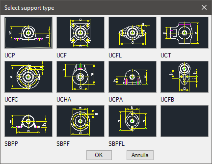
Tabella 14. Supports Library Standard Table
UCP |
UCF |
UCFL |
UCT |
UCFC |
UCHA |
UCPA |
UCFB |
SBPP |
SBPF |
SBPFL |
|
As for all standard libraries, it is possible to create a part and insert automatically in the material’s slip the details used. The code of the support’s part is customizable by editing the value in the appropriate space. If the box is left empty, the code will be created automatically.
Click on Codify Menu and a dialogue box appears and allows the user to select a specific support between all those codified.
- What
- A dialogue-box to set the type of support to use, its view and its insertion parameters.
- Why
- For the correct drawing of the support, with the abovementioned tables, without necessarily insert all the entities which compose the support, but selecting in the available list the line with the essential characteristics as the length, the width, etc…
- How
- The dialogue-box opened with the command Top_Supporti is divided in four main sectors.
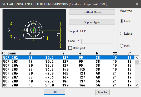
The one on the top left acts on the image, thus click on the left side to modify the type of chain, or on the right side to modify its view. The available views are: Front, Lateral and Plan. Or select the button "Type of Support" which opens a dialogue-box displaying all the available types of supports.
Under this button there is a text line with the currently selected object and its view. Once confirmed the type of support to place in the drawing, just insert the object’s layering point and insertion angle.
(Dialogue...) Insertion Point: Insertion Angle: