Top_TollQuote

Dimensional Tolerances
Menu: Top > Dimensions > Dimensional Tolerances
- What
- Adds or modifies a tolerance (ISO system) on an existing dimension or text. The text must be a decimal number, or must be preceded by the diameter symbols Ø or M.
- Why
- To insert tolerance values in the dimensions.
- How
- After selecting the dimension a dialogue is displayed to choose the limits. In the first two pages of the dialogue is displayed an image on the quality and the position to chose with different kinds of couplings. To scroll pages up and down press the buttons Next and Previous.
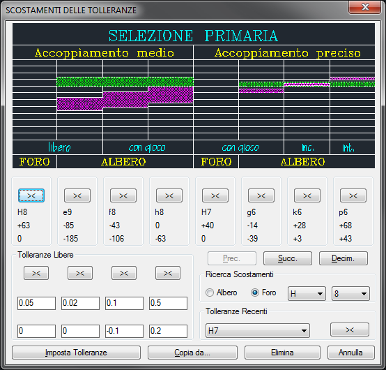
In the image in the dialogue-box are 8 columns which contain, starting from the bottom, the lower limit, the upper limit, the code (Position-Quality) and related button. The reported limits are real and given in micron. To choose a code select the button and press OK. Next to the dimension are added the code and the limit in millimetres, which are reported in brackets.
To insert limits not restraint by a code, select in the area associated to the Free Tolerances the button associated to the desired values. The values (given in millimetres) under the buttons can be modified and saved to be used again.
It is possible to select the tolerance value to insert in a list which includes the last limits inserted to quicken selection. With the button Copy from… is possible to get with a simple selection from a dimension present in the drawing the tolerance value to insert.
|
Importante |
The tolerances apply the same style of the dimension and the same type of text, thus, to modify the tolerance features act on the AutoCAD variables. |
![[Importante]](lib/imgimportant4.png)
The same thing for the text's style. If the dimension was created with a different text style, reset the old style, then run the command.
|
Nota |
A dimension modified with its tolerances can be stretched and the limits updated with the new value. |
![[Nota]](lib/imgnote40.png)
|
Nota |
The tolerances work correctly only with the decimal system of measurement. |
![[Nota]](lib/imgnote39.png)
|
Nota |
The limits are read by the customization file SCOST.PRS. The file SCOST.PRS is a text file the user can customize with any file editing programme. Thus, it is possible to insert limit codes not set as default, or increase the limit values for an existing code. In the file, closed in square brackets, there is the code Position- Quality. Next to it there is the value of the dimension and under it all the other values. The first two are the limit value of the dimension, e.g. if they are 50 and 80, the value must be over 50mm and smaller or equal to 80mm. The other two values are the limits in micron corresponding to the measure. [H8] 1,3;+14,0; 3,6;+18,0; 6,10;+22,0; But there are some rules to follow:
|
![[Nota]](lib/imgnote38.png)
In the dialogue is also the button Decim, which modifies the number of decimals used to write the limits. The default value is 3 and, to avoid to write useless zeros, blank all final zeros and set the AutoCAD environment variable: dimzin = 8.
The button Erase Tolerance erases from the selected dimension the tolerance.
The adjacent button named Set Tolerance allows to set the dimension tolerance insertion mode. If you click on the button, the following dialogue is displayed:
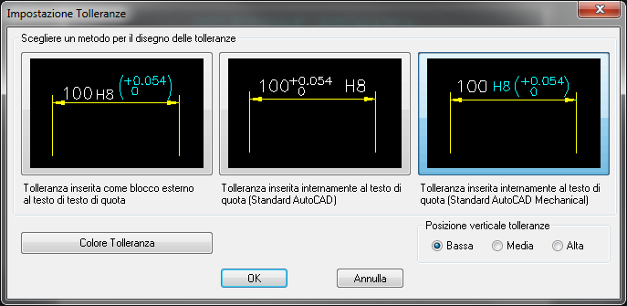
Click on the first button to insert the tolerance in the dimension as a block external to the dimension text; click on the central button and the tolerance is inserted in the dimension text with a graphic mode different from the previous. The third button, active by default, inserts the tolerance in the dimension text with a graphic mode complying to the UNI standards of the first case.
IMPORTANT: the tolerances referring to texts are always inserted as external blocks. In this dialogue, the button at the bottom left changes the tolerance text colour, while the radio button on the right changes the height of the text position respect to the dimension line.
|
Importante |
If the dimension value does not correspond to the actual dimension, the tolerances are inserted out of the dimension text, since it is not possible to display with the AutoCAD dimension style a dimension value different from the real one associated to a tolerance. |
![[Importante]](lib/imgimportant3.png)
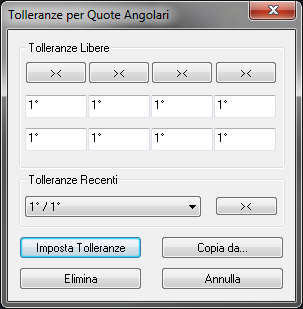
If you enter the tolerance command and select as reference dimension an angular dimension, a dialogue will be displayed where to insert the tolerance on the angle as for the tolerances on the lengths. Insert free tolerances in the top section, while at the centre, for a quicker selection, there is a drop-down menu including the last tolerances inserted by the user.
Within the buttons at the bottom, the button "set tolerances" opens the same window previously described; the button "Copy from"… copies the tolerance of a given angular dimension; the button "Erase" erases the tolerance when the selected dimension has already a tolerance.