Topx_FrameBuilder

Frame Builder
- What
- Display all features of the frame module.
- Why
Allows you to plan 3D frames for parts using the TOP profiles library
- How
Launched the command it shows the main dialog of the frames generator
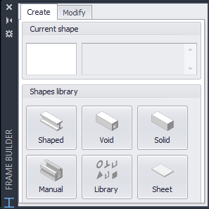
In the upper part, the commands for managing the profile libraries are shown. In the central part, the beam insertion commands are available and, in the lower part, the joint editing commands.
Library
The library include the three families available in the 2D part.
- Shaped profiles
- Hollow profiles
- Solid profiles (bars)
A user library and the possibility to select a profile from the drawing are added to the three base libraries.
Other than these the command to draw metal sheet is exposed as well.
Standard libraries show the same 2D interface conveniently appropriated to disable the option that does not apply to 3D.
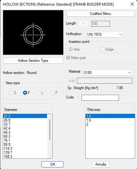
The user can select the desired standard and it will remain active until a new configuration is selected or when exiting the program.
Customized libraries can be made very easily creating drawings containing blocks of the desired profiles. The base point of the block will be used as a reference point of the profile in extrusion phase.
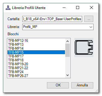
The command allows selecting the profile to use by showing a small preview of the profile and the block name to facilitate selection.
With the option “manuale” it is possible to select directly a profile in the current drawing.
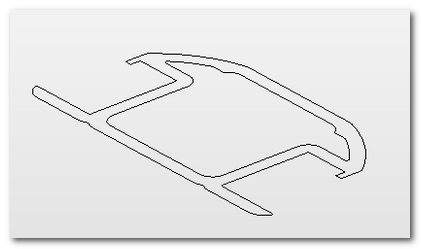
The profile must be closed and made by poly-lines or curves (lines, arcs, splines, ...). The program automatically identify the presence of internal holes.
Profiles addition
Profiles can be added in two ways:
- By two point
- Following a path
The insertion command by two points requires selecting the two points (start/end) and draws the beam using as path the line passing through the two points and using the profile insertion point.
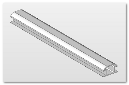
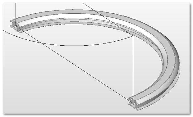
In this case obviously the profile is always straight. Using any curve as path it's possible to make shaped profiles (even if they can't truly be made).
There is a command for multiple insertion that let's you select all tracks and make automatically all the beams in just one operation.
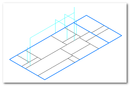
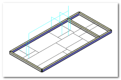
This let's you build your own frame in a few easy steps.
Insertion options
The profiles insertion options are the following:
- Rotation angle - it let's you define the rotation angle around the profile axis.
- Offset - it let's you indicate the offset from the natural termination points of the beam according to the path or the indicated points.
Modify
The drawn beams are normal solids, so they can be edited with normal CAD tools. To ease the standard processing the module have available some commands to speed up the modification and the joints processing.
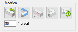
For the normal modification are available the following commands
Rotation
It let's you rotate a profile around the reference path. It's possible to insert the rotation angle in the reference slot. The rotation occur according to the right hand rule considering the beam direction.
|
|
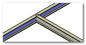
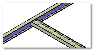
In the illustrations the result of a 90 degrees rotation.
Alignment
The alignment command allows aligning two profiles using planar faces as references.
Imagine to have 4 beams. Two beams are rectangular section bars while two bars have a triangular section.
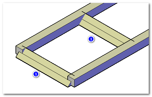
It may not be immediate to measure the correct rotation angle to align the hypotenuse face of the triangular section with the top face of the rectangular profile. In this case, the alignment command is useful.
The command asks for the face to align and the reference face (or three points) and rotates the selected beam until the indicated faces become coplanar (if a solution exists).
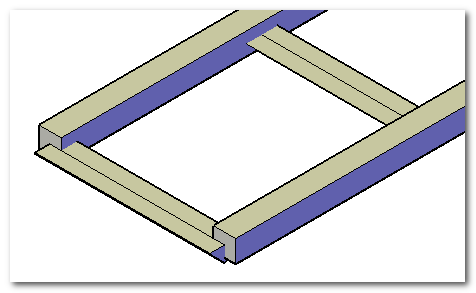
The result of the example is illustrated in the image.
Delete beam
The delete beam command is a modified “delete part” that automatically filters only “beam” parts. The command deletes the parts and consequently the solids contained in them.
Join beams
The “join beams” command merges the selected solids and creates a single resulting part. The parts of the merged beams are automatically deleted.
Update beams registry
The update beam data command recalculates the physical properties of the beams and updates the part data to keep correct information for bill of materials generation. See the dedicated paragraph for more details on data management.
Joints processing.
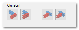
Angular connection
The angles can be processed in two ways:
- Butt joint (aligned contact)
- Miter joint
The gap processing let's you align the profiles against each other.
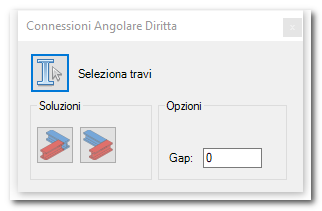
The software asks to select the beams and propose the first available solution. It's possible to modify the solution selecting the specific button. Optionally it's possible to insert a gap between the two beams.
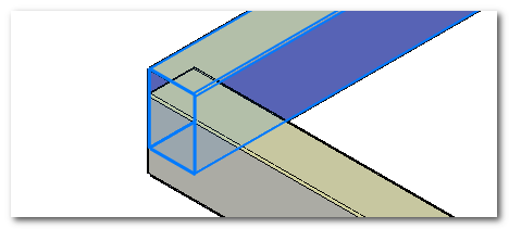
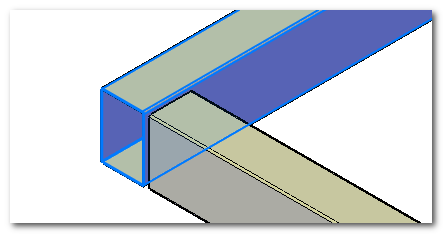
In case you'd want cancel the operation it's enough to use the CAD cancel command.
To do a miter processing press the specific command. The command shows a dialog with the main options.
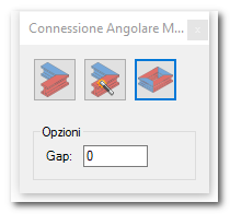
The first option is the single miter and it requests the selection of the two beams involved in the processing. It is possible to indicate a gap to maintain between the two beams in this case as well.
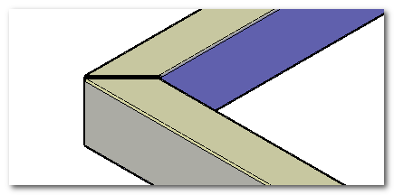
The second option is the "automatic single miter" and it requests the selection of just one beam. If the beam have some interference on the final points with other beams they are processed automatically.
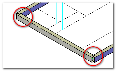
In the example two interferences can be seen on the final points. In this case it's enough to select the main beam to obtain the processing of both sides.
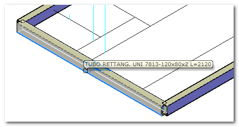
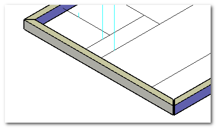
The final result is as follows
The last option is the multiple miter that let's you select a whole frame and generate an automatic solution based on the reciprocal interference.
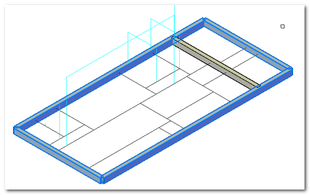
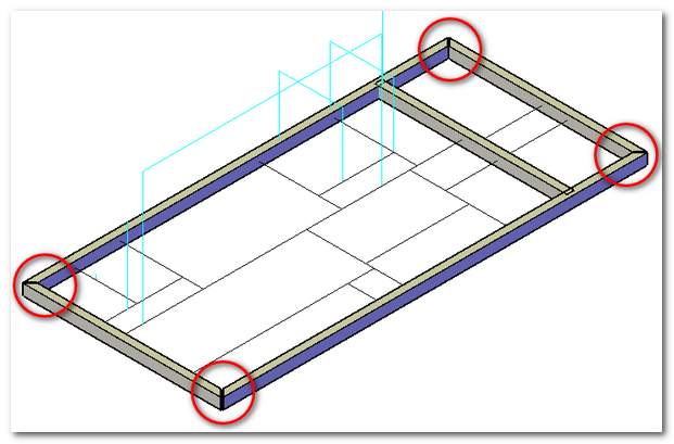
Obviously the selection has to be done by being careful not to select halfway intersections otherwise the results are not foreseeable.
T connection
Intermediate T-joints are normally solved by shortening or trimming the beam “in butt”. In the case of standard shortening, the software displays a configuration panel.
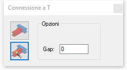
Two options are available:
- Manual selection
- Automatic selection
With manual selection, you must select the reference beam and then the beams to be trimmed.
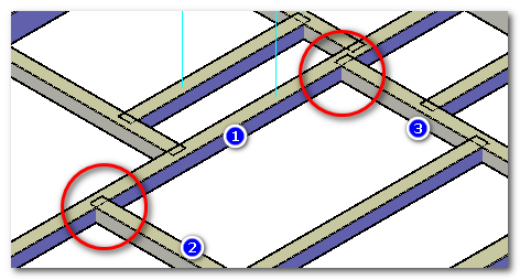
The command allows processing multiple beams simultaneously. The final result is shown.
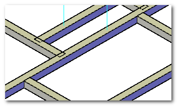
The command remains active when ending the processing waiting for more selections.
The second option (Automatic Selection) uses the interface to automatically know the shortening limits and ease the command use because it requests just one selection.
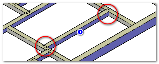
The command will shorten the beam until the limit of the two adjacent beams.
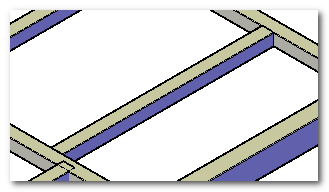
An optional gap is available to maintain the gap between the two adjacent beams.
Connection with Machining
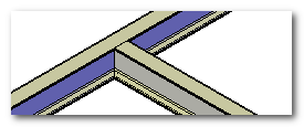
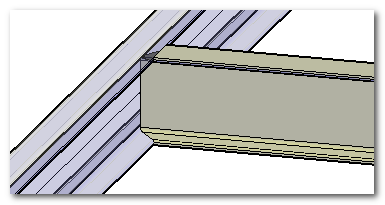
For shaped profiles (e.g., IPN), the connection often requires a shaped cut.
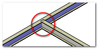
In this case, the machining cut command can be used.
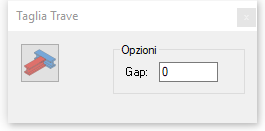
The program asks for the cutting beam and the beams to be processed. Optionally, a gap can be defined between the two solids.
|
|
Tools
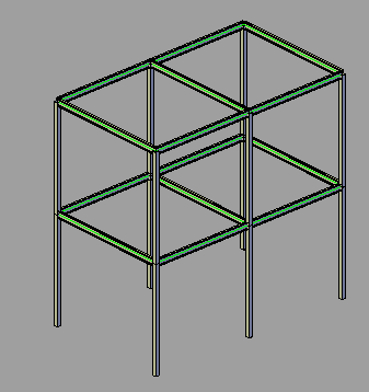
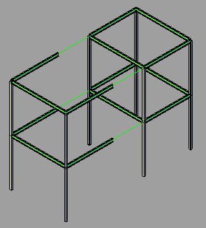
 Frame Associativity
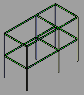
The frame generator can create associative models with a skeleton. Modified parts are replaced by new components, so previous modifications are lost.
Initial model |
Stretch operation on the frame |
Update |
|
|
|
Part data
For each generated beam, a part is created containing the solid and related information.
Part name
The main information is the part name that shows in the browser for parts.
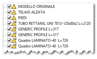
The creation of the part's name is automatic and it follows a template defined in TOPX.PRS file to allow to reach variable tile related to the length. In the illustration the generated names for various types of profiles can be seen.
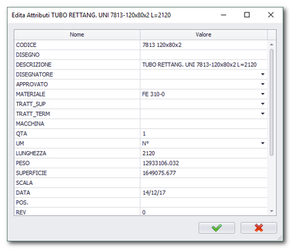
Other than the part's name other information are memorized.
Code
The standard code, in case of a library, is automatically calculated and it follows the same rules of 2D libraries.
Material
The material can be assigned automatically at the same exact way of 2D. If there is an aspect (material) in CAD with the same name it's automatically set.
Length
The length is automatically calculated by the program and it's used to update the description.
Weight
The weight is automatically calculated if physical properties (density) are indicated. If they're not assigned it's used the default value.
Surface
It's automatically calculated by the program.
Bill of Materials
The frame module adds two new BOM types to TOP.
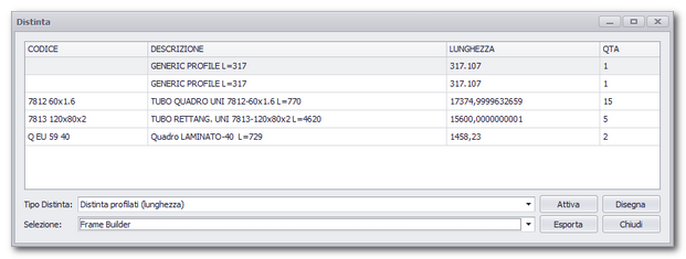
Profile BOM (Length)
This BOM groups beams by code and sums lengths and quantities. This allows estimating the number of parts and total raw material length.
Profile BOM (Machining)
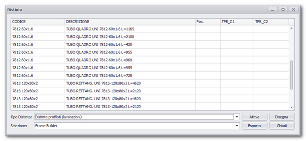
The machining BOM lists individual beams (not grouped), indicating beam code, description, position (if ballooned), and head/tail machining details if present.