Top_Boccole

Bushes
A convenient function for drawing bushes is provided to the user.
To define the type and the corresponding parameters of the joint, a simple and intuitive dialog box is available, which can be accessed via the dedicated commands described later.
As with all other standardized libraries, it is possible to create a part so that the used components are automatically included in the bill of materials. The part code for the bushing can be customized as desired by editing the value in the appropriate field.
If this value is not provided, the code will be generated automatically.
By activating the Coding Menu button, a dialog is opened that allows the user to select a specific bushing from among only those that have been previously coded.
What
Displays a dialog box in which it is possible to define the type and specific parameters of a bushing to be inserted to size in the drawing.
Why
The command is used for the correct drawing of bushings with standard-compliant dimensions by selecting the desired row from those available.
How
The dialog box opened by the command is divided into four main sections.
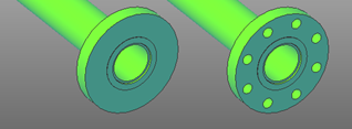
In the first section, located at the top left, the user can change the insertion view of the bushing by clicking directly on the preview image. The available views are: Section and Front View.
The type selection is made by choosing the desired component from the corresponding popup list located below the bushing preview image.
Once the component to be inserted into the drawing has been confirmed, the user only needs to specify the insertion point and the insertion angle of the object.