Spotlight
To help users recognize and manage parts, a color-coding system known as Spotlights has been implemented.
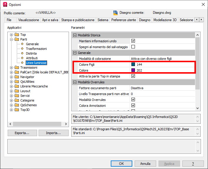
Under normal operation, the active part is displayed using its original colors, parts at the same or higher hierarchical level are displayed in purple (color 202), while parts at a lower hierarchical level are displayed in light blue (color 144).
Using the "Spotlights" command on the status bar, it is possible to disable Spotlights or configure them to color all geometries not belonging to the active part using the same color.
These options affect the entire application. This means that it is not possible to configure Spotlights differently for multiple drawings opened in the same CAD session.
Through the application's Options menu, it is possible to modify the colors used for Spotlight visualization.
In addition to the standard behavior, it is possible to force the base Spotlight color using the commands Top_Color_Prt and Top_NewPrtSlColor
Besides the Spotlight color, it is also possible to adjust the brightness level to "dim" parts other than the active one while preserving their original colors, making the active part easier to identify.
This mechanism differs from the CAD platform's LAYLOCKFADECTL setting because it is not based on the locked state of layers.
Spotlights are a display-only feature. Under normal conditions, when printing the drawing or opening it in a CAD system without the application installed, geometries appear using their original colors.
Printing Spotlights
To print drawing geometries using Spotlight colors, it is possible to use the CAD status bar and change the setting of the "Print Spotlights" variable.
It is a multi-level setting:
- Disabled : Default setting. Spotlights are ignored during printing.
- Enabled : The drawing will be printed exactly as it appears on screen.
- Forced Only : Geometries will be printed using the Spotlight color only if it has been explicitly forced by the user; otherwise, their native colors will be used.
- Forced or Black : Geometries will be printed using the Spotlight color if it has been explicitly forced by the user. Parts without a forced color will be treated as black.
Note
To avoid different results depending on the active part, it is possible to force activation of the TOP part before printing from the Qs Mechanical Suite Options menu.
Saving Spotlights
To make Spotlight colors visible to users who do not have Qs Mechanical Suite installed, it is possible to force the saving of Spotlight colors. When this option is enabled, geometries are physically assigned the colors in which they are currently displayed at save time. Depending on drawing size, this operation may require a significant amount of time.
Note
At the end of the save operation, the color assignment is undone. This causes the drawing to be marked as modified and therefore unsaved in the CAD environment.