Component insertion
Insertion
pressing the confirm key from the piping menu you procede to the insertion of the component in the drawing area. Every element of the library has typology and insertion options, the most commons are below.
- insertion for connector: This is the base typology for the software. It asks to select a connector for the positioning of the component. the connector specifies the verse of the component. it is not necessary to select the connector. it's sufficient to select de solid, near the connector, it will be recognized automatically.
every piping component has a connector for every important spot. For example the strainght pipe, has two connector, one for every end.
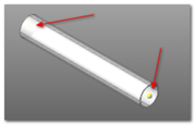
the selection happens "touching" the component "near" the connector.
when you insert a component, this will be inserted on the selected connector, starting from his base connector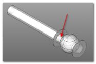
every time you want to add a part of the tube, the connector will be shown automatically
- Insertion for point and direction: connectors are not always available for the auto-attachment of the components. in some cases it's necessary to insert manually the component with direction and insertion point.
in this case you'll be asked the insertion point and , after that, the direction following the principal axis through the selection of the second point in relation at the insertion point.
- custom pipes profile: The software consent to create straight pipes ad elbows with custom profiles.
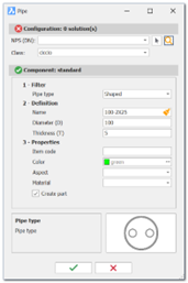
For these components, the pipe definition profile must be indicated. Profiles are defined in the environment within the "piping\shapes" folder. For each profile, both a DWG file and a PNG preview file must be provided. The profile name should be entered into the database.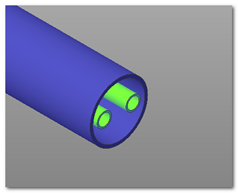
For proper functionality, the profile must consist of regions that the software will extrude to the correct length value. The color of the region will be maintained as the pipe's color.