top_smarttag

Dynamic Attribute Management
What
The command allows you to manage, through a dedicated interface, the definition of dynamic attributes (SmartTag) for the current drawing.
SmartTags are special connections that can be made between an attribute of a part and a drawing entity of that same part . Through a library of functions, expandable through LUA, it is possible to link any type of entity to an attribute and vice versa.
Why
This can be useful to ensure that a particular attribute always remains up to date following changes to the drawing.
For example, you can make the "LENGTH" attribute associated with a line or dimension, so that when it is stretched the attribute is updated accordingly.
How
It is necessary to enable the use of dynamic attributes from the Qs Informatica options menu, otherwise a message will be shown to the user.
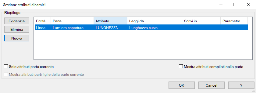
When the command is launched, the user is shown a window containing a summary of the links found in the current drawing. Obviously, if no SmartTags have been defined in the current drawing, the interface appears empty.

Dynamic Attributes Definition Phase
The " New " button allows you to define a new SmartTag in the current drawing: the dialog is temporarily hidden to give the user the possibility to select an entity from the drawing. When the entity is selected, the dialog is re-proposed, with the new entity in the central summary.
The first and second columns are locked and show, in order, the type of entity selected and the name of the part it belongs to.
The following columns are freely editable by the user and are necessary to define the characteristics of the SmartTag.
In order, the third column ( Attribute ) allows you to select the attribute that you want to control from the selected entity. Clicking in the white space displays a drop-down menu from which you can select the desired attribute. The check at the bottom right of the dialog, " Show attributes filled in the part ", allows you to filter the drop-down list so that you only see the attributes filled in the part to which the entity is aggregated. You can insert an attribute that is not in the list by right-clicking inside the cell.
The fourth and fifth columns of the summary allow you to select LUA functions defined in the " smartTag.lua" file .
Specifically:
The fourth column allows you to select the operation to be performed to fill in the attribute when the reference entity changes.
The fifth column is the selection of the operation that will be performed each time the reference attribute changes.
It is not strictly necessary to define a two-way link: you can choose to create the link only between entity and attribute or only between attribute and entity, all at the user's discretion.
The last column , useful if a dynamic block has been selected, allows you to control a particular parameter with each variation of the reference attribute.
Control phase \ summary of dynamic attributes
Once our set of SmartTags has been defined, this window also takes on the task of summarizing and managing the connections created.
In fact, when we have connections already defined, the controls will be unlocked:
- Highlight: Highlights in the graphics area the entity associated with the selected row in the summary.
- Delete: Allows you to delete the definition of a dynamic attribute.
Filters will also be made available at the bottom that allow you to isolate rows that refer to the current part , or the current part and any children .
Use
It is possible to define links of this type only between an entity and an attribute of the same part in which it is located; it is not possible to define links between entities and attributes of different parts.
BricsCAD parameter support
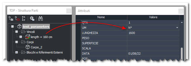
The Dynamic Attributes panel allows you to align a part attribute to a parameter in a BricsCAD parametric block.

The feature allows you to "link" a part attribute to a global BricsCAD "constraint/parameter".

The function to use is "Entity Parameter". When the option is selected, a panel appears showing all the parameters connected to the selected entity. Selecting the parameter and confirming creates the connection.
Limitations
Using global parameters makes sense only in the current drawing. These parameters are automatically renamed by BricsCAD when the dwg is loaded into another drawing. In this case the link is broken and must be restored manually.
User parameters are not supported.