top_pall

Ball Part
What
Ball a part and set the POS. attribute according to the entered value.
Why
To perform the so-called "ballooning": that is, each part is indicated with a dot containing a number, then each dot can be matched with a row in the table (see the Top_Dis_Tab command ).
How
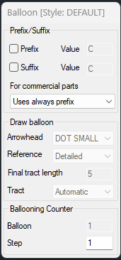
After launching the command, a dialog appears that allows you to customize the insertion of the dot.

In the dialogue you can decide whether to use the prefix or the suffix (editable in the respective “Value” windows) or to have the prefix or the suffix automatically used only if you are highlighting a Commercial part.
It is also possible to define the terminal type (Dot, Small Dot, Full Arrow, Empty Arrow, Open Arrow, None) and decide whether to insert the dot into the drawing, attach it to an existing dot or just set the POS. attribute of the part without drawing the dot.
“final stroke length” allows you to add an orthogonal segment to the end of the ball connection and “stroke direction” indicates its development which can always be vertical, always horizontal or managed automatically based on the orientation of the ball.
The “Dot value” item displays the current progressive; however, it is possible to modify it to force the dot value as desired or, using the “increment” item, it is possible to give an increment step so that the numbering occurs “step by step”.
In the ballooning options shown on the command line there is the Multiple Selection which allows you to sequentially balloon a user-defined multiple selection of parts.
In the balloon options shown on the command line there is Align which allows you to align the inserted bullet to an existing bullet.
In the ballooning options shown on the command line there is Select which allows you to balloon the objects in the selection
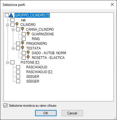
The List option instead allows you to view the entire list of parts in which the user can note the parts already highlighted and can select the parts to highlight with a mouse click.

After OK when the dialog is closed, the selected parts are highlighted sequentially as for multiple selection.
You can also populate parts in BricsCAD mechanical views.
In layout space, you select the “MEcview” option and indicate the view geometries that reference the 3D objects in the model.

To simplify the shot-peening operation, a badge is displayed next to the selection pointer to indicate whether the part has already been shot-peened or not.
No geometry |
Part to be shot |
Shot-peened part |
|
|
|
The green badge indicates that the part needs to be shot peened, while the red badge indicates that the part has already been shot peened.
This functionality is subject to the CURSORBADGE option in AutoCAD.
Note
- Among the options of the ballooning style there is the possibility of setting the assembly ballooning . When it is active the user has no constraints in managing the progressive numbering and in the table the quantities of similar parts are added only if they have the same position attribute. This type of ballooning is useful for ballooning the so-called "exploded views", that is drawings with the representation of how the assembly of a certain component should take place, in this case it can be useful to balloon parts depicting identical pieces, with different numbers, for the pure convenience of describing the project, or because such parts actually represent different components although identical. The compilation of the table, after a ballooning of this type, to add the parts will not take into account the ballooning value, and the code, and only if these are identical will it perform a sum.


