Top_Calettatori

Shrink
Ribbon: Top Mechanical Draw > Mechanical Library > Feather > Shrink
A useful function to draw locking sets.. The locking sets available in the dialogue-box are TOLLOK.
Tabella 22. Shrink Library Table
TLK 110 |
TLK 130 |
TLK 131 |
TLK 132 |
TLK 133 |
TLK 134 |
TLK 200 |
TLK 300 |
TLK 400 |
|
They are all compatible with those of other locking set producers as BIKON, RINGFINDER…
To quickly set the type of locking set, its mode and the other parameters, a simple and intuitive dialogue-box is opened with the appropriate commands described hereinafter.
As for all standard libraries, it is possible to create a part and insert automatically in the material’s slip the parts used. The code of the locking set’s part is customizable by editing the value in the appropriate space.
If the box is left empty, the code will be created automatically. Click on Codified Menu and a dialogue box appears and allows the user to select a specific locking set between all those codified.
- What
- Displays a dialogue-box to set the type and the specific parameters of a locking set to insert in the drawing.
- Why
- For the correct drawing of locking sets, with standard dimensions, by selecting in the appropriate list the mode and the desired line with the essential characteristics.
- How
- The dialogue-box opened with the command Top_Calettatori is divided in four main sectors, as described in the image below.
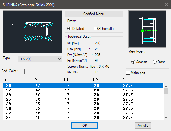
On the top left is displayed, as for most libraries, the preview of the locking set according the type of view, modifiable clicking on the image, and the type of locking set.
In this section, select the type of locking set in the drop-down menu, and add, modify or consult the component’s code to be added to the part’s enhancements.
In the central section there is the button for switching from the main menu to the menu codify, as previously described.
Under is displayed a list-box to select the drawing mode (Complete or Schematic), a dialogue-box to consult all technical data not part of the graphic parameters.
On the right section, the image allows to select the layering mode. Under, select the component’s type of view, and choose if to insert the object as a part.
In the low-central section is displayed the graphic parameters to set the object to insert.
Once selected all options, set the insertion point and angle and press OK to insert the object in the drawing.
(Dialogue...) Insertion Point: Insertion Angle: