Topx_LoadPrt

Menu: Top3D > Carica Parte...
- What
- Permette di caricare un componente esterno (DWG) definito per parti e posizionarlo nel progetto corrente.
Loads an external component (DWG) defined for parts and arrange it in the current project.
- Why
- Il comando TOPX_LOADPRT permette di eseguire un “carica parte 3D”. Il comando è stato studiato appositamente per caricare un modello 3D e posizionarlo correttamente.
- The command TOPX_LOADPRT permits to do a “load 3D part”. The command has been studied specifically for loading a 3D model and arrange it correctly.
- How
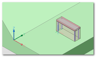
- Lanciato il comando viene chiesto il posizionamento all'interno del progetto corrente
- Ha le stesse funzionalità di un normale “carica parte” ad esclusione della richiesta del fattore di scala e offre le seguenti funzionalità aggiuntive
- Launched the command it asks the positioning in the current project.
- it has the same features as a normal "load part" except for the request of the scale factor and it offers the following extra features
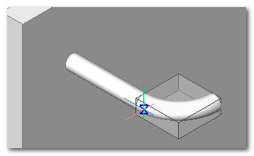
Riconoscimento del piano di appoggio
Il comando riconosce automaticamente il piano di appoggio del figurino al variare della posizione del puntatore del mouse. TOP identifica la geometria sottostante e ne determina il piano di riferimento in modo automatico adattando l’UCS di conseguenza.
Identification of the support plane
The command recognise automatically the support plane of the model when changing the position of the mouse cursor. TOP identify the underneath geometry and determine its reference plane automatically adapting the UCS as outcome.
Una volta definito il piano di appoggio si può premere il tasto SHIFT per bloccare il piano di appoggio. In questo modo il piano rimarrà definito anche al variare delle geometrie sottostanti.
Definizione automatica dell’ingombro
In fase di inserimento della parte viene automaticamente disegnato l’ingombro esterno dello stesso in semitrasparenza. Questo aiuta nel posizionamento della parte all’interno del disegno.
Punto di posizionamento variabile
Durante la fase di inserimento il punto di riferimento può essere modificato premendo il tasto TAB. Normalmente vengono considerati i seguenti punti: punto di inserimento della parte, punti inferiori ingombro esterno.
Once defined the support plane the SHIFT key can be pressed to block the support plane. This way the plane will remain defined even when changing the underneath geometries.
Automatic definition of ____
In the part insertion phase it automatically draws the external ___ in translucence. This helps in the positioning of the part inside the drawing.
Variable positioning point
During the insertion phase the reference point can be modified by pressing the TAB key. Usually the following points are considered: point of part insertion, inferior points external ___.
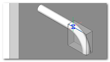
Flip orientamento
Durante la fase di inserimento è possibile modificare la normale (asse Z) del componente premendo il tasto CTRL.
Orientation flip
During the insertion phase it is possible to modify the normal (Z axis) of the component by pressing CTRL key.
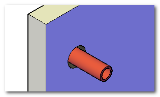
Sottrazione automatica
Le parti caricate possono essere predisposte per eseguire una lavorazione di svuotamento sulla parte di destinazione. Questo può essere utilizzato per creare una “sede” per la parte caricata; si pensi al foro di passaggio di un tubo o di un bullone oppure alle fondamenta per il basamento di un macchinario.
Automatic subtraction
The loaded parts can be arranged to do an emptying operation on the destination part. This can be used to make a “location” for the loaded part; such as the transition hole of a pipe or a bolt otherwise at the foundation for a machinery base.
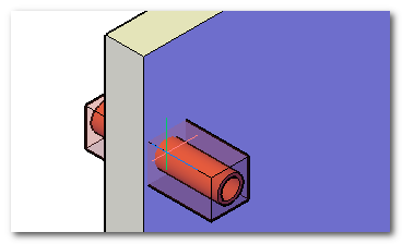
Per eseguire la sottrazione automatica è sufficiente creare una sottoparte di nome “.sub” all’interno della parte da inserire. I solidi 3D definiti all’interno di questa parte verranno utilizzati per realizzare un’operazione booleana nel disegno di destinazione.
To do the automatic subtraction it's enough to make a sub-part named “.sub” inside the part that has to be inserted. 3D solids defined inside this part will be used to make a boolean operation in the destination drawing.
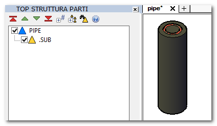
Per identificare il solido da lavorare verrà utilizzato l’ingombro dei solidi di sottrazione.
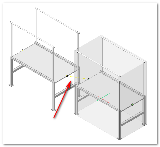
Connessione automatica
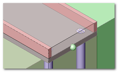
Il meccanismo di caricamento 3D supporta i connettori delle parti. In fase di caricamento vengono evidenziati con una sfera colorata i connettori dei componenti per facilitare l’aggancio.
To identify the solid ___ will be used the ____ of the subtraction solids.
Automatic connection
The 3D loading mechanism support the part connectors. In loading phase the components connectors are highlighted by a coloured sphere to simplify the hooking.
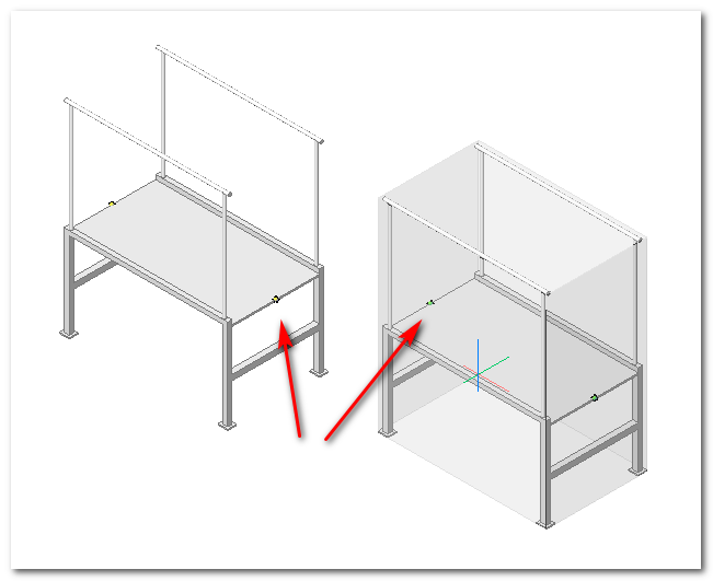
Quando si avvicinano due connettori viene evidenziata una linea elastica che mostra il possibile aggancio. Avvicinando ulteriormente i componenti si ottiene l’effettivo aggancio degli stessi.
When two connectors are approaching an elastic line that shows the possible hooking is highlighted. Drawing near the components the conclusive hooking effect take place.
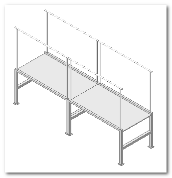
Una volta agganciati i componenti i connettori vengono eliminati dal disegno.
Once the components are hooked they get deleted from the drawing.
In fase di inserimento dei componenti è possibile orientare la parte inserita attorno all’asse di inserimento premendo il tasto CTRL. Viene eseguita una rotazione di 90° ad ogni pressione del tasto.
In the components insertion phase it is possible to steer the inserted part around the insertion axis by pressing CTRL key. A 90° rotation is done after every key pressing.