Top_SpecialDim

Special Dimensions
Ribbon: Top Annotations > Dimensions > Special
- What
- Generates different dimensions and inserts or modifies different dimension options with only one command.
- Why
- To quicken and optimise the dimensioning since the user can find all the necessary just with this command.
- How
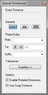
- The command has a double user interface. The main commands are communicated with the control line, while the executed dimension options are inserted in the non-modal dialogue box (see here below).
Enter the command, select the first of the linear dimension line or insert one of the following options: [Angular\COord.\BaseLine\Continuous\ARc\Parallel]<Select>
If you select one dimension point, select also the second, then the command will generate a linear dimension. If the two dimension points are placed on adjacent and consecutive lines, the command allows to carry out a linear dimension, aligned or rotated, by moving the mouse cursor. While I move the cursor to change the dimension, this dimension is always instantly displayed in the dialogue.
If the user does not select a point but presses enter, the command enters in <Select> mode. Thus, it is possible to select a line-, arc- or-circle-type entity. If a line is selected, the command is executed as if the user has inserted as dimension points the ends of the line itself. If an arc or a circle is selected, by inserting the correct option, it is possible to generate a radius, a diameter or a line dimension according to the diameter.
Nevertheless, the linear dimensions inserted with the special dimensions are associated to the entities on which they are placed.
Insert “A”, then press Enter to access the option Angular. In this case is requested as option to select two lines, one arc, one circle or select two points to set the angle to generate an angular dimension.
Insert “AR”, press Enter to access the option Arc, which generates the dimension of the arc’s length. In this case it is also possible to select an arc or its setting points.
Insert “CO” to access the option to generate the ordinate or coordinate dimension. In this case insert the dimension’s origin plus the positioning direction. It is also possible to chose to dimension automatically or manually, with "A" or “M”.
The options BaseLine and Continuous respectively generate the baseline dimension and the continuous dimension, as for the AutoCAD standard commands.
The option Parallel allows to generate quickly the dimension of the distance between two parallel lines.
Besides the control line options, the user can exploit the potential of the non-modal dialogue- box, which allows to modify the dimension’s text, insert a prefix or a suffix just as in Edit Dimension, or underline or frame the dimension’s text.
An important option is the one to insert tolerances, which gives access to a special section of the special dimensions dialogue-box. This option inserts the dimension in the drawing with all the tolerance limits and would not need any further editing. In the dialogue-box are all the same tools as the tolerance management main command: set the tolerance limits, set the free tolerances, insert the list of the recent tolerances, insert the functionality of the tolerance copy, thus set the format of the tolerance to insert.
The option on the use of snap distance allows to place the new linear dimensions which are being inserted at a default distance respect their setting points or their dimensions already present in the drawing and that have the same insertion angle. While dragging the building dimension it will snap and becomes red when near the default distance. The reference distance is obtained from the baseline spacing set in the style of the current dimension.
All the executed dimension subcommands are sequential, thus remain active until the ESC button has not been pressed. Enter now the main command of the special dimensions, which will remain active until the session is not ended by pressing ESC.