Top_Cinghie

Belts
Ribbon: Top Mechanical Draw > Mechanical Library > Gear > Belt
A useful function to draw belts. The types of belts are similar to those previously analysed in the paragraph on the pulleys.
To quickly set the type of belt, its width and the other parameters, a simple and intuitive dialogue-box is opened with the appropriate commands described hereinafter.
As for all standard libraries, it is possible to create a part and insert automatically in the material’s slip the parts used. The code of the belt’s part is customizable by editing the value in the appropriate space. If the box is left empty, the code will be created automatically.
Click on Codified Menu and a dialogue box appears and allows the user to select a specific belt between all those codified.
- What
- Displays a dialogue-box to set the type and the specific parameters of a belt to insert in the drawing.
- Why
- For the correct drawing of belts, with standard dimensions, by selecting in the appropriate list the type, the width, and the desired line with the essential characteristics.
- How
- The dialogue-box opened with the command Top_Cinghie is divided in three main sectors, as described in the image below.
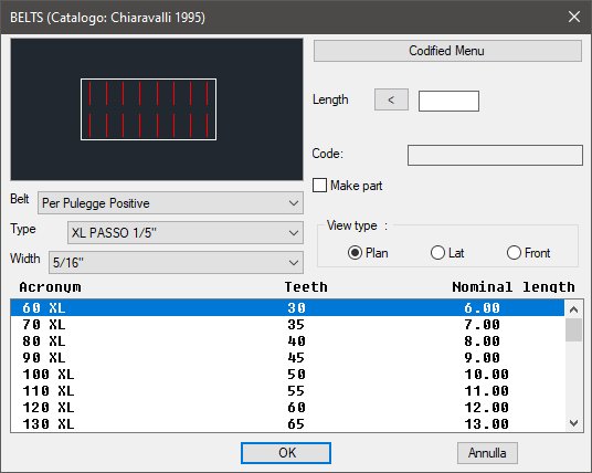
On the top left is displayed the preview of the object selected with the dedicated commands. Click on the image to change the belt’s view. In the same section, under the image, three pop-up lists are displayed to select the belt, or its category, the type, or the type of category, and the width.
In the right section, besides the previously described button Codified Menu, is displayed the part to modify the belt's length. Its dimensions can be entered with the keyboard or selecting to points on screen. In this section is possible to insert and consult the belt’s code, inserted as enhancement while creating the part. The toggle "Make Part" inserts the selected component as a part. Thus, select the belt’s view, which can be: Plan, Lateral or Front.
Select in the appropriate list under those three sections, the parameters necessary to draw the belt. Once confirmed the object to place in the drawing, just insert the object’s layering point and insertion angle.
(Dialogue...) Insertion Point: Insertion Angle: