Top_SimbSald

Welding Symbols
Ribbon: Top Mechanical Draw > Mechanical Annotations > Welding Symbols
- What
- Inserts in the drawing as a block a type of welding triangle.
- Why
- Detects in the mechanical drawing certain welding points.
- How
- Select two points which determine the start and the end of an arrow: one end indicates the welding drawing, the other the data on the welding symbols.
Once set the points a dialogue box is displayed (see in the image below) where the user can insert further data on the welding.
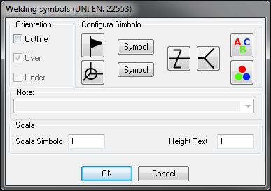
On the right the user chooses the graphic’s colour (the colour of the inserted symbols) and the text colour is inserted next or near the symbols.
In the central part the designer can choose which symbols to insert by selecting or deselecting the 4 images or clicking on the two Symbol buttons which open a sub-dialogue and allows to select the graphic symbols to represent the welding type and insert, if necessary, the appropriate dimensions.
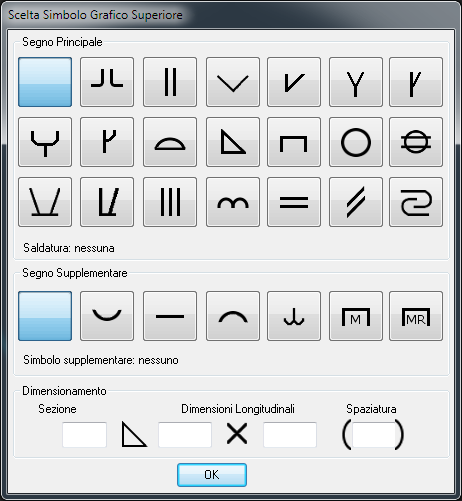
The symbols in this library are in accordance with the UNI standards.
On the left the user can select the orientation and decide to display the discontinuous line above or under the symbols centreline.
If the fourth displayed symbol is inserted, also the note’s drop-down menu is activated which allows to insert the code of the welding type.
In the editbox below are requested the scales for the graphics and the text of the symbol to insert. These values are saved until they are not modified again, even with different AutoCAD sessions, to be constantly available. These values can also be inserted with the Qs Informatica Options Menu.
Done this, press Enter to insert the welding symbol in the drawing.
Command: Top_SimbSald <ENTER> First
point of arrow: (point A) Second point of arrow: (point B)
Dialogue … (ENTER to end): <ENTER>