Top_Raccordi

Fittings
Ribbon: Top Mechanical Draw > Mechanical Library > Fittings
A useful function to draw fittings. The available types are grouped in the following categories:
Tabella 16. Fittings Library Standard Table
VRG |
100 – 101 – 104 – 106 – 107 – 108 – 110 – 113 |
VDG |
205 – 206 – 207 – 208 – 209 – 210 – 211 |
VDN |
200 – 201 – 202 – 203 – 204 – 220 – 221 – 223 |
VDM |
216 – 217 – 229 |
To set the category, the type and the parameters of one of the fittings, a simple and intuitive dialogue-box is opened with the appropriate commands described hereinafter.
As for all standard libraries, it is possible to create a part and insert automatically in the material’s slip the parts used. The code of the connector’s part is customizable by editing the value in the appropriate space. If the box is left empty, the code will be created automatically.
Click on Codified Menu and a dialogue box appears and allows the user to select a specific connector between all those codified.
- What
- Displays a dialogue-box to set the category, the type and the specific parameters of a fitting to insert in the drawing.
- Why
- For the correct drawing of standard fittings, with the abovementioned tables, without necessarily insert all the necessary values to set the object, but selecting in the available list the desired line containing the standard essential characteristics.
- How
- The dialogue-box opened with the command Top_Raccordi is divided in three main sectors.
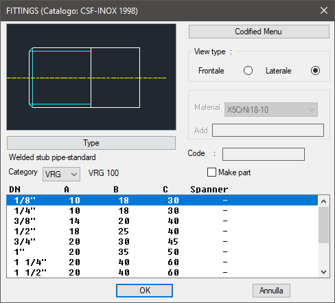
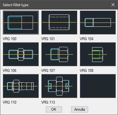
The one on the top left allows to select the type of connector by selecting the category and the type. The category is set directly in the available list; while the type is set entering the button "Type", or modifying the left side of the image.
Click on the right side to set the view type. Select the button "Type", under the image, to open a new dialogue-box with the type of connectors available according to the selected category.
On the top right part of the main dialogue-box is possible to set the view of the connector. Right under there is a space to set the connector’s dimensions. Once confirmed the type of connector to place in the drawing, just insert the object’s layering point and insertion angle.
(Dialogue...) Insertion Point: Insertion Angle: