Top_Molle

Springs
Ribbon: Top Mechanical Draw > Mechanical Library > Springs
A useful function to draw springs.
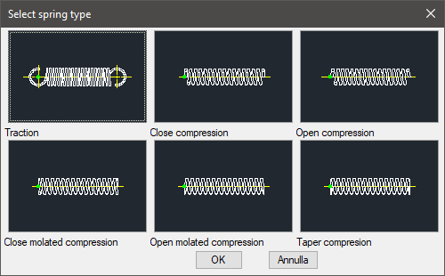
To set the type of spring, a simple dialogue-box is opened with the appropriate commands described hereinafter. The available types of springs are: Tension, close Compression, open Compression, close ground Compression, open ground Compression, tapered Compression.
As for all standard libraries, it is possible to create a part and insert automatically in the material’s slip the parts used. The code of the spring’s part is customizable by editing the value in the appropriate space.
If the box is left empty, the code will be created automatically. Click on "Codify Menu" and a dialogue box appears and allows the user to select a specific spring between all those codified.
- What
- A dialogue-box to insert the object in the drawing is displayed to set the type of spring, its view and its parameters. It is also possible to set the spring to place as at rest or in working position (in the latter specify if in tension or in compression). For all springs, except tension springs, is possible to calculate the dimensions.
- Why
- To insert a spring in the drawing, set the descriptive parameters or select those previously saved (if existing) in the dedicated list.
- How
- The dialogue-box opened with the command Top_Molle is divided in three main sectors.
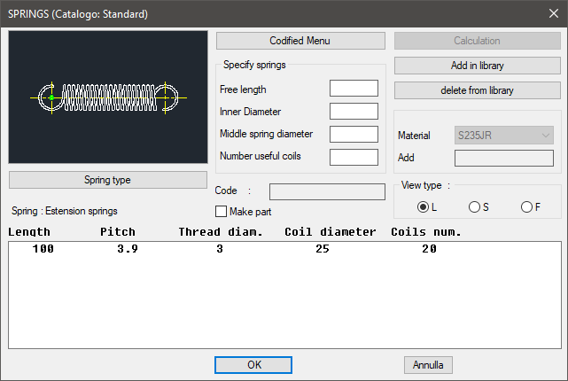
The one on the top left acts on the image, thus click on the left side to modify the type of spring, or on the right side to modify its view. The available views are: Lateral, Sectional and Front.
Or select the button "Type of Spring" which opens a dialogue-box displaying all the available types of springs.
Under this button there is a text line with the currently selected object and its view.
On the bottom right of the main dialogue-box there is a box to set the material to associate to the part created. In the centre of the main dialogue-box there is a box to insert the necessary parameters to draw a spring: unloaded length, wire’s diameter, average diameter of the coils and the number of active coils. These parameters are referred to the spring at rest.
Once set the parameters, these can be saved with the button "Add in Library" and then use them directly from the list, without having to re-insert them again. Once confirmed the spring to place in the drawing, another dialogue-box is displayed to insert a spring at rest or in compression (or in tension for the tension spring).
Now just insert the object’s layering point and insertion angle. To calculate the spring, insert the parameters in the main dialogue-box and select the button "Calculate".
It is possible to modify the spring’s main parameters (e.g. modulus of elasticity, specific gravity, etc…) in the dialogue-box displayed on screen. Press the button OK and insert spring’s drawing with the description of its calculation.
Demonstration: Calculate the compressed helicoid spring of a water safety relief valve.
The valve taken in consideration in the previous drawing, is usually used in high-pressure car-wash systems.
The plan provides the use of this valve in a system with 200bar pressure. Up to this pressure, the valve must remain closed, and opens when the pressure exceeds this value.
Set the thrust diameter “Ds” at 8mm, calculate the thrust area “As” at (8/2*8/2)*3.14 = 50.26mm. With P = 200 bar = 20 N/mm, calculate the corresponding load on the spring with L1 conditions (valve closed): at L1 = 20*50.26=1,005 N.
With the Ds diameter at 8mm, set the opening of the valve, with mechanic end stop, with "a” = ¼ “Ds” = 2mm. At this point, without knowing each value, we know that the difference L1 – L2 = 2mm.
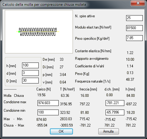
Set the following parameters of the spring:
- The maximum applied Tau torsion stress (L2) must be inferior to 1,000 N/mm, take in consideration the material used and the operating conditions (in this example is consideration a material Module elastic. Tang. G = 81,500 N/mm).
- The L2 value must be 1 to 2 mm greater than the close-wound spring’s length.
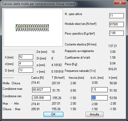
According to our experience and to the pre-set dimensions, let’s try to give the following values:
Wire’s diameter |
d = 4 mm |
Spring’s average diameter |
D = 12 mm |
Active coils |
N = 9 |
Spring’s length |
h = 52 mm |
Difference between the spring’s length and the close-wound’s length.
Max. Condition |
d.ch. = 1.5 |
Min. Condition |
d.ch. = 3.5 |
Set as boundaries the minimum and maximum length of the spring according to the close- wound spring’s length, to calculate the forces under the different conditions.
As displayed in the previous dialogue-box, the Tau, in Max. Condition, is greater than the 1,000 N/mm value, thus the spring is not acceptable.
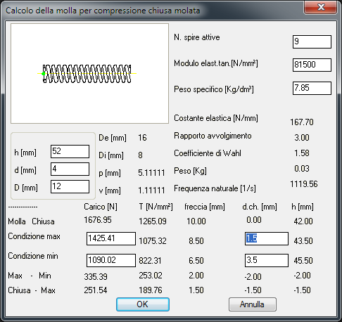
Lets try to change the number of active coils from 9 to 11. We obtain:
To set the load’s value in Min. Condition at 1,005 N, increase the spring’s unloaded length.
Thus, change the value “h” (spring’s unloaded length) bringing it to 61 mm.
The programme recalculates the values, as displayed in the following dialogue-box:
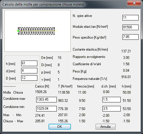
The Tau has decreased under 1,000 N/mm, thus the spring is considered acceptable. Press OK to insert the spring in the drawing. Insertion Point: (select a point in the drawing)