Top_Lamiere

Sheets Metal
Ribbon: Top Mechanical Draw > Mechanical Library > Semifinished > Sheets Metal
With TOP the user disposes of a series of standard self-tapping and self-penetrating screws that can be managed using a simple and intuitive dialogue box.. The manageable parameters are the diameter, the length and the type of the screws end.
As for all standard libraries, it is possible to create a part and insert automatically in the material’s slip the parts used. The code of the screw’s part is customizable by editing the value in the appropriate space. If the box is left empty, the code will be created automatically.
- What
- Allows to draw the plates with lateral, front or top view.
- Why
- To insert in a drawing a plate, and possibility to create different parts and manage the elements in the material’s BOM.
- How
- A dialogue-box displaying the plate’s main parameters is opened to easily and rapidly draw a sheets metal.
The dialogue-box opened with the command Top_Lamiera is described in the image below.
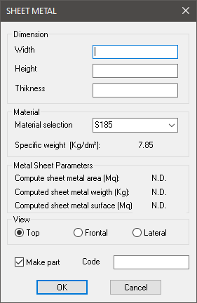
In the sector at the top is displayed a dialogue-box with the plate’s dimensions. It is possible to insert in the drawing the plate’s width, height and the thickness.
Right under there is another dialogue-box to select and insert material. Below are displayed the parameters the application calculates according to the part’s dimensions, and according to the selected material, which are the area, the weight and the surface.
Still under there is the command to select the component's view. And there is the command to create a part, and a dialogue-box to insert the code created according to the plate’s thickness and material.
Once selected all options, set the insertion point and angle and press OK to insert the object in the drawing
Example 155. Draw Sheets Metal
(Dialogue...) Insertion Point: Insertion Angle: