Top_SvLam

Metal Sheets Developments
Ribbon: Top Mechanical Draw > Mechanical Library > Flat Patterns
With TOP the user disposes of a library of standard plate developments with preset geometries that can be managed using a simple and intuitive dialogue box. This command inserts only the graphical developments, namely is it does not analyze the registries.
The geometries to insert in the drawing are inserted in the current part.
- What
- Displays a dialogue-box to select the reference geometry from which create the plate development.
- Why
- For the correct drawing of metal sheets development given the construction geometries and dimensions.
- How
- A dialogue-box executing automatically the calculations and drawing the geometries is opened to easily and rapidly draw the plate developments. The dialogue-box opened with the command Top_Svlam is quite simple.
On the left side are displayed a number of buttons to select the geometry from which obtain the development. Under is displayed a static preview with the dimensioned drawing of the selected geometry, as described in the dialogue’s image.
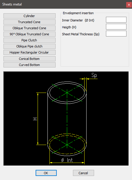
On the top right insert the dimensions which describe the geometry to create the development. For each geometry, each voice in the list changes.
Once set the parameters, press the button ok to place the plate development in the drawing.
Example 160. Draw Metal Sheets
(Dialogue...) Insertion Point: Insertion Angle: