Top_QuoteFori

Dimension Holes
Ribbon: Top Annotations > Dimensions > Plates
- What
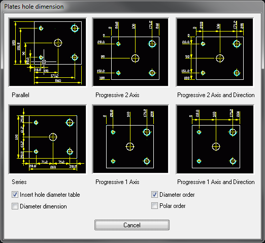
- To dimension holes or geometrical points, including polygons (e.g. holed plate). Dimensions can be generated on one or two axis (one perpendicular to the other).
In the holes are dimensioned the distances between the centres and the origin of the dimensions. The command can create a table including the progressive numbering of the holes and their diameter (not for the additional points).
After drawing the dimensions and selected the option "Insert table on holes’ diameter", the holes, but not the additional dimensions, are automatically numbered, and a table is created indicating the number and the diameter of each hole. Insert the table in the desired point (vertex at bottom left as positioning point) or press WSC to interrupt the command and get the drawing of the dimension, but not of the progressive numbering or of the hole’s table.
For the older versions, this table is a block, while for the AutoCAD versions later than 2007, this table is an actual AutoCAD table. If the user has set on QSTABFORI a customized table style, it will be used to draw the table. To make older drawings compatible, even with the most recent CAD versions, the user can draw the table as a block with the option "use AutoCAD table in punched plates".
- Why
- To quicken and simplify the dimensioning of holes or geometrical points inserted in the plate.
- How
- Indicate if to draw a table (selection boxes at the bottom left), click on the image of the desired dimension, select the holes to dimension (also the ISO and GAS threaded holes are recognised), add to the selection the dimension additional points, set the dimension origin (0.0).
Set the direction of the X and Y axis (ends of the plate) if the plate is rotated (only for parallel or series dimension), and then the dimensions layering point (part of the plate where to draw the dimensions). With the options in the dialogue-box it is possible to order the holes in the table according to their diameter or, in case of a perforated flange dimension, according to the polar order.
It is also possible to generate a diameter dimension of the selected holes.
Command: Top_QuoteFori <ENTER> …
Dialogue-box… Select holes of the plate… Select additional points:
<ENTER> Select additional points: <ENTER> Origin of
reference system: _int of Direction axis X: _int of Direction axis
Y: _int of Insert dimensions according to axis X: Insert
dimensions according to axis Y: Insert table (press <Esc>
not to insert): <ENTER>
|
Nota |
In case of series dimension, also the overall dimension is drawn. |
![[Nota]](lib/imgnote51.png)
|
Nota |
Not all holes are dimensioned. If two or more holes are perfectly aligned, there is no use to dimension them, thus only the hole the closest to the dimensions' position is dimensioned (see example above). |
![[Nota]](lib/imgnote50.png)
|
Nota |
If a dimension line overlaps a hole’s symmetry axis, the dimension’s point of departure will be moved to the end of this axis. |
![[Nota]](lib/imgnote49.png)
|
Nota |
The holes are ordered according to the direction of the X axis and, if they have the same position, according to the direction of the Y axis. |
![[Nota]](lib/imgnote48.png)
|
Nota |
An empty space is left in the generated table, next to the diameter, to insert the tolerance with the command TOP_TOLLTESTI. |
![[Nota]](lib/imgnote47.png)
|
Nota |
When the table positioning point is requested, press Esc not to draw the number of the holes and the table. |
![[Nota]](lib/imgnote46.png)