Top_Dadi

Draw Nuts
Ribbon: Top Mechanical Draw > Mechanical Library > Screw > Nut
With TOP the user disposes of a series of standard nuts that can be managed using a dedicated dialogue box.. The only important parameter to draw a nut the user can modify is the diameter.
Tabella 4. Nut Standards Table
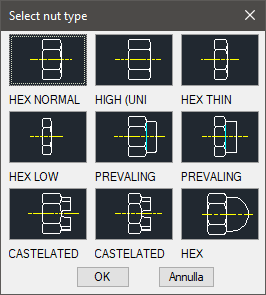
Hexagonal High |
UNI 5587 |
Hexagonal Normal |
UNI 5587 |
Hexagonal Low |
UNI 5587 |
Hexagonal Thin |
UNI 5590 |
Elastic Stop Normal |
No specific UNI Standard |
Elastic Stop Low |
No specific UNI Standard |
Castle Normal |
UNI 5594 |
Castle Low |
UNI 5594 |
Ball Seat |
UNI 5721 |
- What
- Displays a dialogue-box to select a drawing of a nut.
- Why
- To insert in a drawing a nut conform to UNI standards, and possibility to create two parts and manage the elements in the material’s BOM.
- How
- In the dialogue-box are displayed: a list of the diameters available for the selected nut; an image of the nut (in plan view or two- or three-paned lateral); the button Nuts… to select the type of nut to draw; the button Washers… to select the washer to add to the nut.
Select one of these buttons and a dialogue- box is displayed to select on the images the element (nut or washer). Once made the selection, enter the main dialogue-box to confirm the selection or to modify the type of nut to draw.
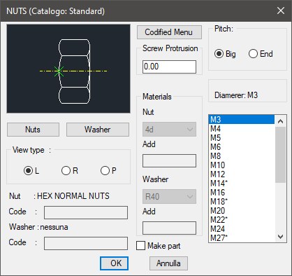
Insert in the text-box "Screw’s Nibs" the nib of a screw’s shank to draw with the nut.
The user can also use: a button to confirm the creation of the parts and a list created in order to choose the type of material to be used for the nut and possible washers.
The codes of the part of the nut and washers can be customized editing the values in the specific spaces. If such spaces are left empty, the codes will be created automatically. Click on "Codify Menu" and a dialogue box appears and allows the user to select a specific nut between all those codified.
The interface proposed by the dialogue-box is optimal to manage a specific standard drawing. Select the nut and insert the layering point and the object’s angle. Both can be set with the pointing device.
Command: Top_Dadi <ENTER> (Dialogue...)
Insertion Point: Insertion Angle <0>: <ENTER>
|
Nota |
The plan view is displayed in such way in the nut is screwed a screw, since it is useless to draw a nut without the screw. |
![[Nota]](lib/imgnote74.png)
|
Nota |
The dialogue-box described to select the washers is similar to the one for the command Top_Rosette. |
![[Nota]](lib/imgnote73.png)
|
Nota |
In case a castle nut is selected, the length of the pin is requested in a small dialogue-box which is displayed after the main dialogue has been closed and before the screw drawing (see command Top_Viti). |
![[Nota]](lib/imgnote72.png)