Top_CilPneum

Draw Pneumatic Cylinders
Ribbon: Top Mechanical Draw > Mechanical Library > Pneumatic > Pneumatic Cylinders
With TOP the user disposes of a series of standard pneumatic cylinders that can be managed using a simple and intuitive dialogue box..
Tabella 23. Pneumatic Cylinders Library Table
cylinder |
ISO 6431 |
microcylinders |
ISO 6432 |
As for all standard libraries, it is possible to create a part and insert automatically in the material’s slip the parts used. The code of the cylinder’s part is customizable by editing the value in the appropriate space.
If the box is left empty, the code will be created automatically. Click on Codified Menu and a dialogue box appears and allows the user to select a specific cylinder between all those codified.
- What
- Displays a dialogue-box to set the type and the specific parameters of a cylinder to insert in the drawing.
- Why
- For the correct drawing of pneumatic cylinders, with standard dimensions, by selecting in the appropriate list the type, the version, and the desired line with the essential characteristics.
- How
- A dialogue-box displaying the pneumatic cylinder’s main parameters is opened to easily and rapidly draw a plate. The dialogue-box opened with the command Top_CilPneum is divided in four main sectors, as described in the image below.
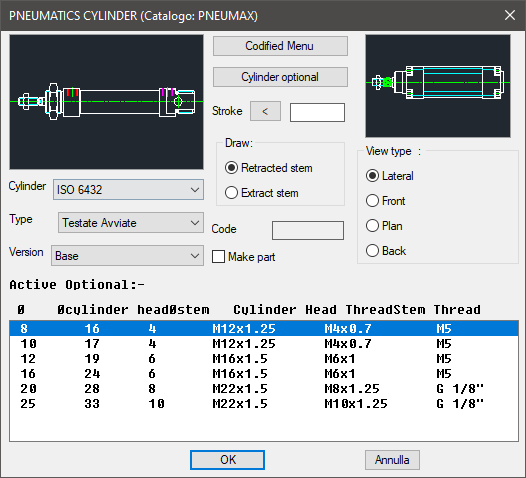
On the top left is displayed the preview of the object selected with the dedicated commands. Click on the image to change the cylinder’s view.
In the same section, under the image, three pop-up lists are displayed to select the cylinder, or its standards, the type, or the type of category, and the version which identifies its configuration.
In the central section is displayed the button Codified Menu, as previously described, and the part destined to modify the cylinder’s stroke. Its dimensions can be entered with the keyboard or selecting two points on the screen. This value must be given.
Under the button to switch to the Codified Menu there is the cylinder’s option button to open a little dialogue-box and select the component’s manufacturing options. In the same section, is possible to select how to draw the piston-rod and, usually, select the cylinder’s drawing mode.
According to the drawing’s requirements, it is possible to draw the piston-rod extracted from the cylinder’s body. In the second partition is also displayed the part destined to insert the codes of the pneumatic cylinder.
The toggle "Make Part" inserts the selected component as a part. On the right section, select in the drawing the cylinder’s layering point. Under this image is possible to select the cylinder’s view, which can be: Lateral, Front, Plan or Rear.
Under these three sections, select in the appropriate list the parameters necessary to draw the cylinder and display the active options the moment a cylinder is selected.
Once confirmed the object to place in the drawing, just insert the object’s layering point and insertion angle.
Example 156. Draw Pneumatic Cylinders
(Dialogue...) Insertion Point: Insertion Angle: