Top_Barre

Bars
Ribbon: Top Mechanical Draw > Mechanical Library > Semifinisched > Bars
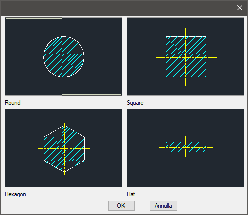
A useful function to draw standard bars. The available types of bars are: Round, Square, Hexagon and Flat.
A dedicated dialogue-box is opened to set the type and the parameters of the bar.
As for all standard libraries, it is possible to create a part and insert automatically in the material’s slip the parts used. The code of the bar’s part is customizable by editing the value in the appropriate space called "Code". If this space remains empty, the code will be created automatically.
- What
- A dialogue-box to insert the object in the drawing is displayed to set the type of bar, its view and its parameters.
- Why
- For the correct drawing of standard bar, with the abovementioned types, describing the main characteristics as the width, the height, etc…
- How
- The dialogue-box opened with the command Top_Barre is divided in four main sectors.
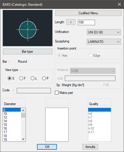
The one on the top left allows to select the type of bar, just clicking on the icon with the object’s preview, or entering the button "Type of Bar". Click directly on the left side of the image to modify the type of bar, on the right side to select the type of view. The available views are: Sectional, Front, Lateral and Plan. Select the button "Type of Bar" under the image to open a new dialogue-box displaying all available types of section bars, thus select one as current. Under this button there is a text line with the name of the object currently selected.
On the top right side of the dialogue-box is possible to set the current length, the material, the standards and the supply to associate in case a part is to be created. In this area, as for the section bars, is displayed the specific gravity of the selected part, which depends on the selected construction material. To add a new material, insert its name and its specific gravity. To know the specific gravity, the surface and the section of the part is important to automatically insert the weight enhancement.
Standards and supply are correlated with the type of selected bar. As already seen for the hollow sections, the layering point can be placed on the axis or on the corner.
In the case of Round and Hexagon, it can not be modified and is fix on the axis. In the bottom part of the dialogue-box is displayed the list of bars with their parameters, divided in three columns. It is possible to display them using the vertical scroll bar and select the most appropriate bar. If a part is created, the value to select in the quality column is associated to the bar.
On the left column is described the diameter, for the Round; the thickness for the Square and Hexagon; the length for the Flat. Click on Codify Menu and a dialogue box appears, and allows to select a specific bar between all those codified.
Once confirmed the type of bar to place in the drawing, just insert the object’s layering point and insertion angle.
(Dialogue...) Insertion Point: Insertion Angle: