Top_AccessCp

Draw Accessories for Pneumatic Cylinders
Ribbon: Top Mechanical Draw > Mechanical Library > Pneumatic > Cylinders Optional
With TOP the user disposes of a series of accessories for standard pneumatic cylinders that can be managed using a simple and intuitive dialogue box..
The available accessories for cylinders.
Tabella 24. Accessories Cylinders Library Table
cylinders |
ISO 6431 |
microcylinders |
ISO 6432 |
compact cylinders |
ISO 21287 |
As for all standard libraries, it is possible to create a part and insert automatically in the material’s BOM the parts used.
The code of the accessory’s part is customizable by editing the value in the appropriate space. If the box is left empty, the code will be created automatically.
Click on Codified Menu and a dialogue box appears and allows the user to select a specific accessory between all those codified.
- What
- Displays a dialogue-box to set the type and the specific parameters of an accessory of a pneumatic cylinder to insert in the drawing.
- Why
- For the correct drawing of pneumatic accessories, with standard dimension, by selecting in the appropriate list the type and the desired line with all the dimensions of the cylinder to assemble.
- How
- A dialogue-box displaying the accessories' main parameters is opened to easily and rapidly draw the accessory. The dialogue-box opened with the command Top_AccessoriCp is divided in three main sectors, as described in the image below.
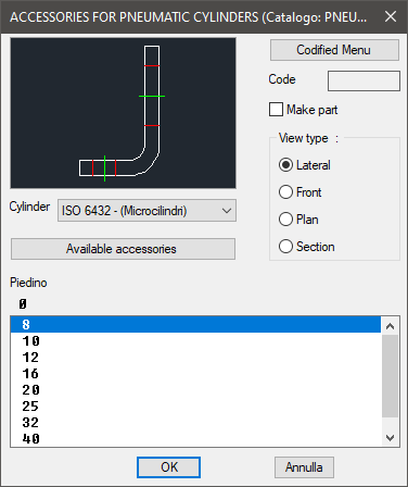
On the top left is displayed the preview of the selected object. Click on the image to change he accessory’s view.
In the same section, under the image, is displayed a pop-up list to select the cylinder, that is the standards of the part on which mount the accessory.
Right under there is the button to access the dialogue-box with all the available accessories of the selected cylinder, as described in the image below.
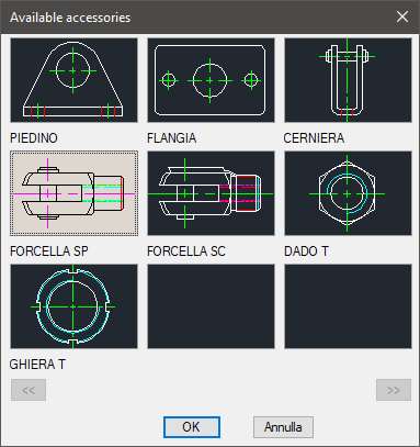
Once selected the accessory, in the main dialogue-box is displayed the complete name.
In the right section is displayed, besides the button Codified Menu described previously, the part destined to insert the code of the pneumatic cylinder. The toggle Make Parts inserts the selected component as a part.
Thus, select the accessory’s view, which can be: Top, Lateral, Front or Section. Under these three sections, select in the appropriate list the dimensions of the cylinder on which mount the selected accessory.
Once confirmed the object to place in the drawing, just insert the object’s layering point and insertion angle.
Example 157. Draw Accessories for Pneumatic Cylinders
(Dialogue...) Insertion Point: Insertion Angle: