SelPulley

Define the Cogged Belt transmission path (Pulleys Selection)
Ribbon: Top Mechanical Draw > Transmissions > Sprocket > Pulleys
- What
- This command allows the user to select the transmission path through the pulleys selection that will compose it. The application interprets a pulley not necessarily as a TOP Pulley, but it associates the concept of pulley with CIRCLES and ARCS by using the centre and diameter values which are considered significant. For each selection the pulley is highlighted.
- Why
- Serves to define the transmission path to calculate and draw, and to define the type.
- How
- By entering the command you are asked to select the pulleys according to the direction of travel of the belt and in a counterclockwise direction. The selection cycle is closed when you reselect a pulley already selected and temporarily displayed on the screen.
At this point the program automatically parameterizes the belt path, but some pulleys may have a wrong direction of travel. For this reason, the program asks which pulleys must be reversed (in order to avoid toothed belt crossing). For each selection, the path is recalculated and displayed.
The selection is considered final by pressing ENTER and the program will make the following checks:
- Check of non-overlapping pulleys
- Check of non-intersecting belt
If all these checks passed successfully, the following interface will be displayed to the user, which will allow him or her to select the belt to use in this transmission. In this dialogue, you will also have an indicative measure of the belt path length, it is possible to change unit of measurement (inches or millimeters) by acting on the control indicating the current unit of measurement.
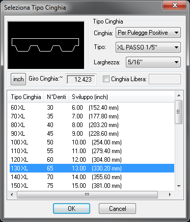
Cogged Belts have default lengths determined by legislation. TOP, nevertheless, provides the user with the possibility to define a belt with a free length, which is not necessarily linked to the legislation. Whatever the length inserted, TOP verifies if it corresponds to the length required to cover the transmission path. If the length does not match, user will be asked to select a pulley to reposition in order to reach the optimal measurement. This is not a mandatory operation (although strongly recommended). If user wants may even refuse to reposition the pulley and leave the belt selected, both whether it is too short and too long.
The program allows you to choose between two relocation methods of sprockets Curve/<Auto>. The method Curve allows you to force the movement of a pulley along any curve of Autocad. This allows you to simulate the movement of a chain tension along shaped slots. The Auto method, command default, defines one movement according to the angle of the pulley with respect to the transmission (Bisector) to balance the load of tension between the two branches of the belt involving it. User will later be asked whether he or she wants to move the whole part, that if the drawing has been properly structured should represent only one entire pulley or only the entity considered as a pulley, which consists in the circle or arc being touched when selecting the round belt.
If everything went well, you will see a confirmation dialogue box.
Comand: _SELPULLEY Selected primitives
diameters counterclockwise [Done]:
<ENTER> Selected primitives diameters
counterclockwise [Done]: <ENTER>
Selected primitives diameters counterclockwise [Done]:
<ENTER> Selected primitives diameters
counterclockwise [Done]: <ENTER>
Select pulley to reverse... <ENTER>
dialogo Select pulley to reposition to
get best measurament... <ENTER>
Tension. Select option [Entity/<Auto>]: A
<ENTER> Tension. Select option
[Entity/<Part>]: