Topx_FrameBuilder

Frame Builder
Menu: Top3D > Generatore telai...
- What
- Questo comando espone tutte le funzionalità del modulo telai.
- Display all features of the frame module.
- Why
- Questo comando consente di progettare dei telai 3D per parti utilizzando la libreria profilati di TOP.
Permit to plan 3D frames for parts using the TOP profiles library
- How
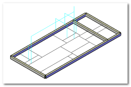
- Lanciato il comando viene mostrato il dialogo principale del generatore telai
Launched the command it shows the main dialog of the frames generator
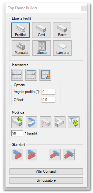
Nella parte superiore sono esposti i comandi per gestire la libreria dei profilati. Nella parte centrale i comandi di inserimento travi e, nella parte inferiore i comando di editazione delle giunzioni
Libreria
La libreria comprende le tre famiglie disponibili nella parte 2D.
- Profilati sagomanti
- Profilati cavi
- Profilati pieni (barre)
Alle tre librerie di base si aggiunge una libreria utente e la possibilità di selezionare un profilo dal disegno stesso.
Oltre a questi viene esposto anche il comando per disegnare le lamiere.
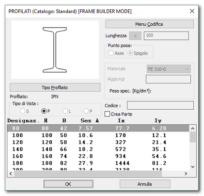
Le librerie standard mostrano la stessa interfaccia del 2D opportunamente adattate per disabilitare le opzioni che non si applicano al 3D.
In the upper part there are exposed the commands to manage the ___ library. In the central part the beam insertion commands and, in the lower part the junction editing commands.
Library
The library include the three families available in the 2D part.
- ______
- ______
- _____
A user library and the possibility to select a profile from the drawing are added to the three base libraries.
Other than these the command to draw metal sheet is exposed as well.
Standard libraries show the same 2D interface conveniently appropriated to disable the option that does not apply to 3D.
L'utente può selezionare lo standard che desidera e questa selezione rimarrà attiva fino alla selezione di una nuova configurazione o all'uscita dal programma.
Le librerie personalizzate possono essere realizzate in modo molto semplice creando dei disegni che contengono dei blocchi con i profili desiderati. Il punto base del blocco sarà utilizzato come punto di riferimento del profilo in fase di estrusione.
The user can select the desired standard and it will remain active until a new configuration is selected or when exiting the programme.
Customized libraries can be made very easily creating drawings containing blocks of the desired profiles. The base point of the block will be used as a reference point of the profile in extrusion phase.
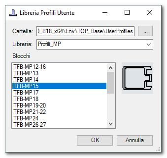
Il comando permette di selezionare il profilo da utilizzare mostrando una piccola anteprima del profilo e il nome del blocco per facilitare la selezione.
Con l'opzione “manuale” è possibile selezionare direttamente un profilo nel disegno corrente.
The command permits to select a profile to use showing a small preview of the profile and the block's name to simplify the selection.
With the option “manuale” it is possible to select directly a profile in the current drawing.
Il profilo deve essere chiuso e realizzato con polilinea o curve (linee, archi, splines, …). Il programma identifica automaticamente la presenza dei vuoti interni.
Inserimento dei profili
I profili possono essere inseriti in due modi:
- Per due punti
- Seguendo un binario
Il comando di inserimento per due punti chiede di selezionare i due punti (inizio/fine) e traccia la trave utilizzando come binario la linea che passa per i due punti e utilizzando il punto di posa del profilo.
The profile must be closed and made by poly-lines or curves (lines, arcs, splines, ...). The programme automatically identify the presence of internal holes.
Profiles addition
Profiles can be added in two ways:
- Through two point
- Following a track
The insertion command through two points requests to select two points (start/end) and trace the beam using as track the line that pass through the two points and using the placing position of the profile.
In questo caso ovviamente il profilo è sempre rettilineo. Utilizzando una curva qualsiasi come binario è possibile realizzare profilati sagomati (anche se non realizzabili realmente).
In this case obviously the profile is always straight. Using any curve as track it's possible to make shaped profiles (even if they can't truly be made).
Esiste poi un comando per l'inserimento multiplo che consente di selezionare tutti i binari e creare automaticamente tutte le travi in una sola operazione.
There is a command for multiple insertion that let's you select all tracks and make automatically all the beams in just one operation.
Questo consente di costruire il proprio telaio in pochi semplici passaggi.
Opzioni di inserimento
Le opzioni di inserimento profili sono le seguenti:
- Angolo di rotazione – permette di definire l'angolo di rotazione attorno all'asse del profilo.
- Offset – permette di indicare l'offset dai punti di terminazione naturali della trave secondo il binario o i punti indicati.
Modifica
Le travi disegnate sono normalissimi solidi, quindi possono essere editati con i normali strumenti del CAD. Per facilitare le lavorazioni standard il modulo prevede alcuni comandi per velocizzare la modifica e la lavorazione delle giunzioni.
This let's you build your own frame in a few easy steps.
Insertion options
The profiles insertion options are the following:
- Rotation angle - it let's you define the rotation angle around the profile axis.
- Offset - it let's you indicate the offset from the natural termination points of the beam according to the track or the indicated points.
Modify
The drawn beams are normal solids, so they can be edited with normal CAD tools. To ease the standard processing the module have available some commands to speed up the modification and the joints processing.
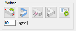
Per la normale modifica sono stati previsti i seguenti comandi
Rotazione
Consente di ruotare un profilo attorno al binario di riferimento. È possibile inserire l'angolo di rotazione nella casella di riferimento. La rotazione avviene secondo la regola della mano destra considerando il verso della trave.
For the normal modification are available the following commands
Rotation
It let's you rotate a profile around the reference track. It's possible to insert the rotation angle in the reference slot. The rotation occur according to the right hand rule considering the beam direction.
|
|
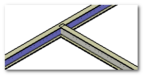
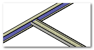
Nelle immagini il risultato di una rotazione di 90 gradi.
Allineamento
Il comando di allineamento consente di allineare due profili utilizzando le facce piane come riferimenti.
Immaginiamo di avere 4 travi. Due travi sono barre a sezione rettangolare mentre due barre hanno una sezione triangolare.
In the illustrations the result of a 90 degrees rotation.
Alignment
The alignment command let's you align two profiles using the plane faces as references.
Imagine to have 4 beams. Two beams are rectangular section bars while two bars have a triangulat section.
Potrebbe non essere immediato misurare rapidamente l'angolo di rotazione corretto per allineare la faccia relativa all'ipotenusa della sezione triangolare alla faccia superiore del profilo rettangolare. In questo caso è utile il comando di allineamento. Il comando chiede la faccia da allineare e la faccia di riferimento (oppure tre punti) e ruota la trave indicata fino a rendere co-planari le facce indicate (se esiste una soluzione).
It could be not immediate measureing quickly the right rotation angle to allign the face related at the hypotenuse of the triangular section to the upper face of the rectangular profile.
In this case it's usefull the alignment command. The command asks the face that has to be aligned and the reference face (or 3 points) and rotate the indicated beam until the indicated faces become co-planar (if a solution exists).
Il risultato nell'esempio è indicato in figura.
Cancella trave
Il comando di cancella trave è un “cancella parte” modificato per filtrare automaticamente solo le parti “trave”. Il comando cancella le parti e di conseguenza i solidi in esse contenuti.
Unisci travi
Il comando “unisci travi” esegue una fusione dei solidi selezionati e crea una sola parte risultante. Le parti delle travi unite vengono eliminate automaticamente.
Aggiorna anagrafica travi
Il comando di aggiorna anagrafica travi si occupa di ricalcolare le caratteristiche fisiche delle travi e aggiorna i dati della parte in modo da mantenere informazioni corrette in fase di creazione della distinta. Vedere l'apposito paragrafo per avere maggiori dettagli sulla gestione dei dati anagrafici.
Lavorazione giunzioni
The result of the example is illustrated in the image.
Delete beam
The delete beam command is a “delete beam” modified to filter just the "beam" parts. The command deletes the parts and as consequence the solids contained inside them.
Connect beams
The command "connect beams" do a fusion between the selected solids and it makes just one resulting part. The united beam parts are automatically deleted.
Update beams registry
The command "update beams registry" handles the recalculating the physical characteristics of the beams and it updates the part's data so that it can maintain the right informations in the ____ creation phase. See the specific paragraph to have more details on the registry data management.
Joints processing.
Connessione angolare
Gli angoli possono essere lavorati in due modi:
- In battuta
- Mitra
La lavorazione in battuta consente di allineare i profili uno contro l'altro.
Angular connection
The angles can be processed in two ways:
- _____
- _____
The _____ processing let's you align the profiles against each other.
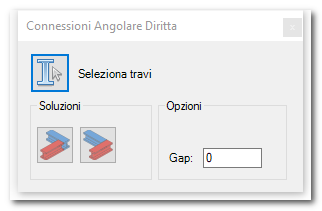
Il software chiede di selezionare le travi e propone la prima soluzione disponibile. È possibile modificare la soluzione selezionando l'apposito tasto. Opzionalmente è possibile inserire un gap (luce) tra le due travi.
The software asks to select the beams and propose the first available solution. It's possible to modify the solution selecting the specific button. Optionally it's possible to insert a gap (light) between the two beams.

In caso si volesse annullare l'operazione è sufficiente utilizzare il comando annulla del CAD.
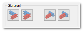
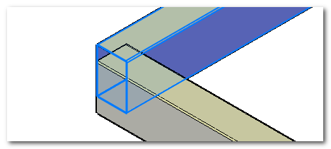
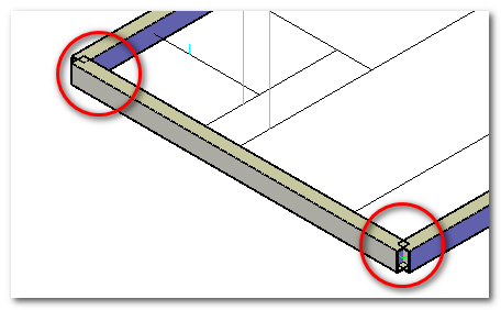
Per eseguire una lavorazione a mitra premere l'apposito comando. Il comando mostra un dialogo con le principali opzioni.
In case you'd want cancel the operation it's enough to use the CAD cancel command.
To do a ___ processing press the specific command. The command shows a dialog with the main options.
La prima opzione è la mitra singola e richiede la selezione delle due travi coinvolte nella lavorazione. Anche in questo caso è possibile indicare un gap da mantenere tra le due travi.
The first option is the single _____ and it requests the selection of the two beams involved in the processing. It is possible to indicate a gap to maintain between the two beams in this case as well.
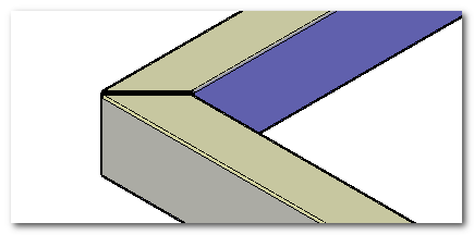
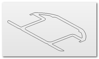
La seconda opzione è la “mitra singola automatica” e richiede la selezione di una sola trave. Se la trave presenta delle interferenze sui punti finali con altre travi queste vengono lavorate in automatico.
The second option is the "___________" and it requests the selection of just one beam. If the beam have some interference on the final points with other beams they are processed automatically.
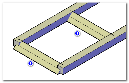
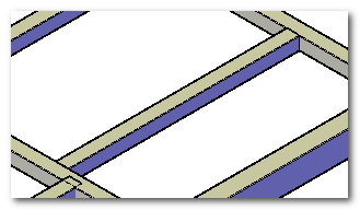
Nell'esempio indicato si può vedere come ci siano due interferenze sui punti finali. In questo caso è sufficiente selezionare la trave principale per ottenere la lavorazione di entrambi i lati.
In the example it can be seen two interferences on the final points. In this case it's enough to select the main beam to obtain the processing of both sides.
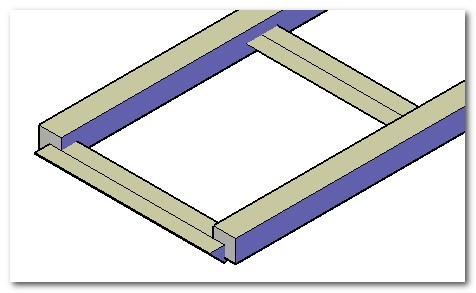
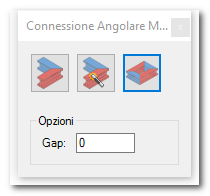
Il risultato finale è il seguente
The final result is as follow
L'ultima opzione è la mitra multipla che consente di selezionare un intero telaio e generare una soluzione automatica basata sulle mutue interferenze.
The last option is the multiple _____ that let's you select a whole frame and generate an automatic solution based on the reciprocal interference.
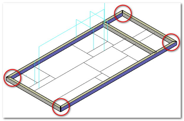
Ovviamente la selezione deve essere eseguita avendo cura di non selezionare intersezioni intermedie altrimenti i risultati non sono prevedibili.
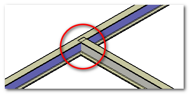
Connessione a T
Le lavorazioni intermedie a T normalmente vengono risolte accorciando o tagliando la trave “in battuta”. Nel caso del normale accorciamento della trave il software mostra un pannellino di configurazione
Obviously the selection has to be done being careful not to select halfway intersections otherwise the results are not foreseeable.
T connection
The halfway T processing are taken care of shortening or cutting off the beam “_______”. In case of the normal shortening of the beam the software shows a configuration panel.
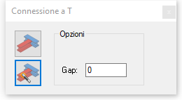
Sono disponibili due opzioni:
- Selezione manuale
- Selezione automatica
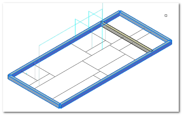
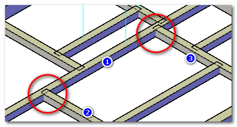
Nel caso della selezione manuale viene richiesto di selezionare la trave di riferimento e poi la selezione delle travi da portare a misura.
Two options are available:
- Manual selection
- Automatic selection
In case of the manual selection it requests to select the reference beam and then to select the beams _________
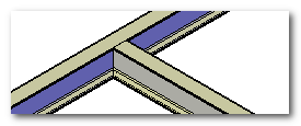
Il comando consente infatti di lavorare più travi contemporaneamente. Il risultato finale è il seguente.
The command permits indeed to work on more than one beam at the same time. The final result is as follow.
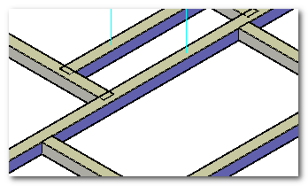
Il comando rimane attivo al termine della lavorazione in attesa di altre selezioni.
La seconda opzione (Selezione Automatica) utilizza l'interferenza per capire automaticamente i limiti di accorciamento e semplifica l'utilizzo del comando perché richiede una sola selezione.
The command remains active when ending the processing waiting for more selections.
The second option (Automatic Selection) uses the interface to automatically know the shortening limits and ease the command use because it requests just one selection.
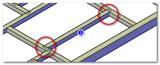
Il comando accorcerà la trave fino al limite delle due travi adiacenti.
The command will shorten the beam until the limit of the two adjacent beams.
È disponibile un gap opzionale per mantenere una luce tra le due travi in battuta.
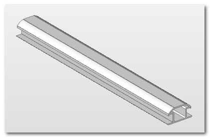
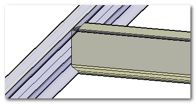
Connessione con lavorazione
Nel caso di profilati sagomati (es IPN) spesso la connessione deve essere fatta tramite un taglio sagomato della trave.
An optional gap is available to maintain light between the two beams in _______
Connection with processing
In case of shaped profiles (Ex IPN) the connection must be often done by a shaped cut of the beam.
In questo caso si può utilizzare il comando di taglio con lavorazione.
In this case the command _______ can be used.
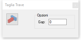
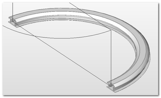
Il programma chiede la trave che effettua la lavorazione e le travi che devono essere lavorate. Opzionalmente è possibile inserire un gap (luce) tra i due solidi lavorati.
The programme asks the beam that realize the processing and the beams that have to be processed. Optionally it's possible to insert a gab (light) between the two processed solids.
|
|
Dati anagrafici
Per ogni trave generata viene normalmente creata una parte contenente il solido e le informazioni relative.
Nome parte
L'informazione principale è il nome della parte che compare nel browser delle parti.
Biographical data
For each generated beam is normally created a part containing the solid and the related information.
Part name
The main information is the part's name that shows in the browser for parts.
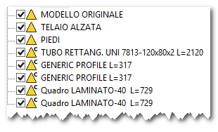
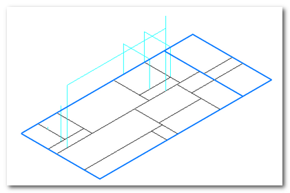
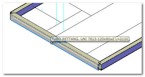
La creazione del nome della parte è automatica e segue un template definito nel file TOPX.PRS per consentire di aggiungere il tassello variabile relativo alla lunghezza. Nell'immagine si vedono i nomi generati per vari tipi di profilati.
The creation of the part's name is automatic and it follows a template defined in TOPX.PRS file to allow to reach variable tile related to the length. In the illustration the generated names for various types of profiles can be seen.
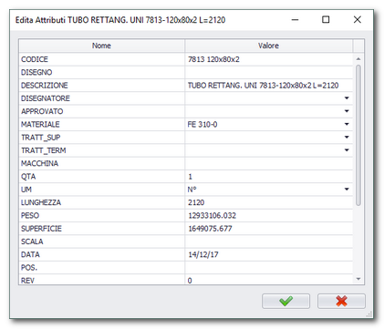
Oltre al nome della parte vengono memorizzate altre informazioni.
Codice
Il codice, nel caso di una libreria, standard viene calcolato automaticamente e segue le stesse regole delle librerie 2D.
Materiale
Il materiale può essere assegnato automaticamente esattamente allo stesso modo del 2D. Se esiste un aspetto (materiale) nel CAD con lo stesso nome questo viene assegnato automaticamente.
Lunghezza
La lunghezza viene calcolata automaticamente dal programma ed utilizzata per aggiornare la descrizione.
Peso
Il peso viene calcolato automaticamente se sono indicate le proprietà fisiche (densità). Se non assegnate viene preso il valore di default.
Superficie
Viene calcolata automaticamente dal programma.
Distinte
Il modulo telai aggiunge due nuove distinte a TOP.
Distinta profilati (lunghezza)
Questa distinta raggruppa le travi per codice e somma le lunghezze e le quantità. In questo modo è possibile stimare il numero di pezzi da generare e la metratura totale del semilavorato.
Other than the part's name other information are memorized.
Code
The standard code, in case of a library, is automatically calculated and it follows th same rules of 2D libraries.
Material
The material can be assigned automatically at the same exact way of 2D. If there is an aspect (material) in CAD with the same name it's automatically set.
Length
The length is automatically calculated by the programme and it's used to update the description.
Weight
The weight is automatically calculated if physical properties (density) are indicated. If they're not assigned it's used the default valor.
Surface
It's automatically calculated by the programme.
Itemized lists
Frame module adds two new itemized lists to TOP.
Profile itemized list (length)
This itemized list gathers the beams by code and sum up the lengths and the amounts. In this way it's possible to esteem the number of pieces to generate and the total surface area of the semi-finished.
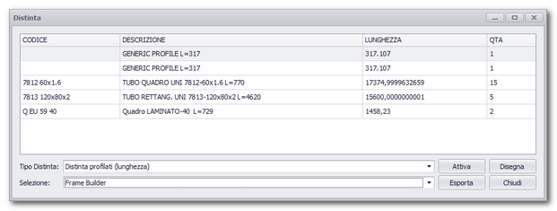
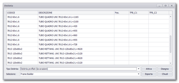
Distinta profilati (lavorazione)
La distinta lavorazioni mostra l'elenco delle singole travi (non sommate) indicando il codice della trave, la descrizione, la posizione (se pallinato) e le lavorazioni di testa e coda se presenti.
Profile itemized lists (processing)
The processing itemized list shows the list of each beam (not summed) indicating the beam's code, its description, its position (if _____) and the head and end processing if present.