Top_Prigionieri

Draw Double-Ended Stud Bolts (Stud Bolts)
Menu: Top > Library > Bolts and Nuts > Stud Bolts...
With TOP the user disposes of a series of standard stud bolts that can be managed using a dedicated dialogue box. The user’s manageable parameters are the diameter and the length. In addition, it is possible to insert a nut, two washers, or a tapped blind or through hole.
This command complies to all the parameters described in the UNI tables, especially for short metal end, medium metal end, long metal end and extra-long metal end studs.
- What
- Draws a stud bolt with the dialogue box.
- Why
- To insert in a drawing a stud bolt conform to UNI standards, and possibility to create different parts and manage the elements in the material’s slip.
- How
- In the dialogue box are displayed the lists of the diameter and of the shank's length, four buttons to select the pitch type of the stud bolt. Four because there could be different combinations of pitch types between the shank and the metal end. The diameter list refers exclusively to the pitch type of the shank and not to the metal end pitch, even though it taken in consideration during the drawing’s management.
In the dialogue-box are different buttons to add, remove or change details in the drawing.
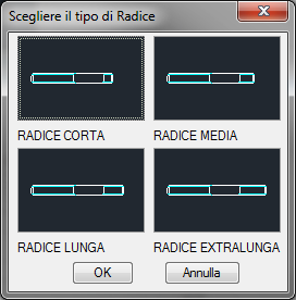
As for the button "Metal End…" which displays a new dialogue-box where are displayed the four types of selectable metal ends. Or the button "Nuts…" which adds or removes a nut from the stud bolt’s shank. Or the button "Washers…" which adds or removes the washer to place under the nut, as described in the previous paragraph on the screws.
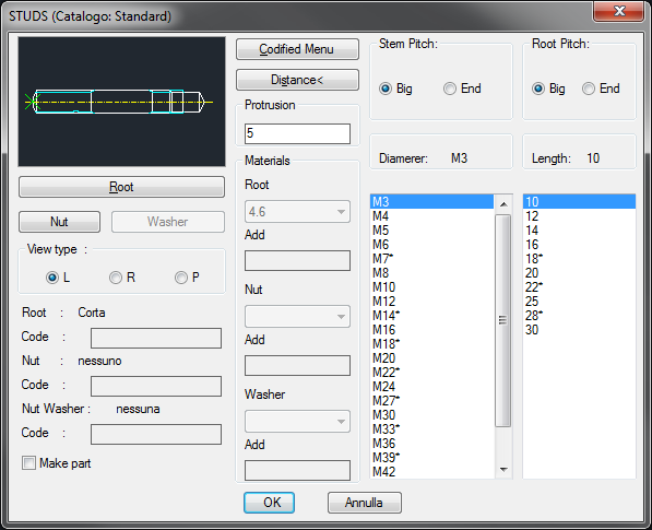
The current metal end type, the type of nut and washer used are displayed on three text lines.
It is possible to modify in the dialogue-box the ideal nib the stud bolt should have from the nut, if placed.
Another important button is "Distance <", which allows to temporarily exit the dialogue box to select the step distance (if there is a nut), or the distance between the shank’s end and the end of the through hole, or the length of the screw. All these lengths can be set by inserting on request the value or two points on screen (in the latter case is the distance between the points) or press ENTER (in this case the length corresponds to the last value inserted). If there is a hole and a nut, the step distance is the distance between the end of the hole and the nut’s base.
It is possible to draw the screw with the two- or three-paned nut. Select the left half of the image which displays the preview of the drawing. Selecting different times on the same half, the screw and its view on the plan will rotate.
To add or remove the hole, select the right half of the image. As default is set a blind hole, but it does not preclude the possibility to insert a through hole or remove each hole.
The user can also use: a button to confirm the creation of the parts and two lists created in order to choose the type of material to be used for the screw, for potential nuts or washers. The codes of the screw part and its relative nut and/or washers, can be customized when the values have been edited in the specific dialogue-boxes. If such boxes are left empty, the codes will be created automatically. Click on Codify Menu and a dialogue box appears and allows the user to select a specific stud bolt between those codified.
Once selected the type of stud bolt to draw, the user must insert the layering point and the rotation angle.
Command: Top_Prigionieri <ENTER> (Dialogue...)
Insertion Point: Insertion Angle <0>: <ENTER>
|
Nota |
In case a castle nut is selected, the length of the pin is requested in a small dialogue-box which is displayed after the main dialogue has been closed and before the screw drawing (see command Top_Viti). |
![[Nota]](lib/imgnote71.png)