Top_DevDd

Double Conveyor
Menu: Top > Library > Conveyors> Double Conveyor
- What
- Displays a dialogue box where you can quickly and accurately define and insert in the drawing a Double Conveyor.
- Why
- It is used to enable the drawing of Double Switch 90 with the automatic creation of parts.
- How
- Designer has at his or her disposal a simple and essential dialogue box that can be divided into two main parts.
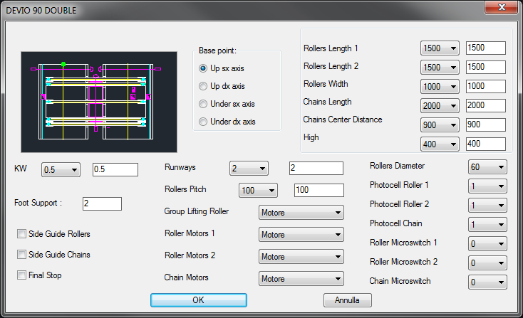
In the upper left corner you see the image that shows a drawing preview with buttons alongside that allow you to optionally set the installation point (left, right, top or bottom). To the right we find some drop-down menus that allow you to set the drawing dimensioning:
- Rollers Length and Width, Chain Lenght and Wheelbase, Height.
At the bottom there is a series of drop-down menus that allow you to define the characteristics of the Double Switch 90:
- KW, Cable Tracks, Rollers Pitch(1), Chain and Roller Motorisation(1), Roller Lifting Group(1), Rollers Diameter(1), Chain and Roller Photocell(2), Chain and Roller Microswitch(2), Standing Legs, Chains and Rollers Lateral Guides, Final Stop.
(1) These values can be set as desired by editing text files included in the application.
(2) If the photocell is activated, the microswitch is deactivated and vice versa.
The drawing of Double Switch 90 is handled by the command TOP_DEVDD which operates in two separate modes depending on whether the Select installation point button is enabled or disabled. In the first case, each time the command is executed one or more Double Switch can be entered iteratively by selecting at each step the installation point as long as you interrupt it by pressing ESC. In the second case only a Double Switch is placed next to the last drawing inserted without requiring the installation point, so that you can easily realize a series of flanked drawings.