Top_Copconi

Couple of straight bevel gear
Menu: Top > Library > Gear > Couple of straight bevel gear
With TOP, the user disposes of a range of bevel gears selected according to the module and the gear ratio to satisfy all the installation and mechanical engineering requirements for the concurrent axis motion transmission.
The outer configuration of the bevel gears complies to the dimension criteria set in the standard DIN 3971. Thus, the prescriptions of the standard DIN 3967 are the most appropriate for the teeth of the bevel gear. The drawing is carried-out ignoring the tooth and giving relevance to the data on the actual overall dimension of the bevel.
The library allows to manage completely the bevel gear’s registry.
- What
- Displays a dialogue-box to select the straight bevel gears to draw.
- Why
- To quickly draw all straight bevel gears.
- How
- Click on the icon to display the library in the abovementioned dialogue-box and select the bevel gear to draw.
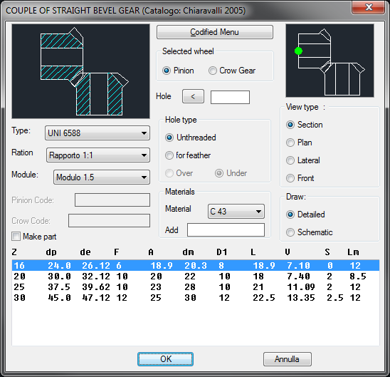
In this order, on the left under the bevel gear’s preview, select the standard to use to draw the bevel gear. The standard will adapted the drop-down menu with the dimension ratio of the gears.
The drive-ratio can change according to the gear’s standards, but, with a 1:1 ratio, two identical wheels, or a pinion and a ring with different dimensions and with similar ratio, will be drawn.
If you select a ratio different from 1:1, two lines with the data on the pinion and the ring will be selected simultaneously The last drop-down menu of this column selects the mode to draw the bevel gears. Under these menu is displayed the tile to create a part for the bevel gear to draw. Then an edit-box is opened to insert a code for the ring and the pinion.
The central column is very important to set the works on the wheel and its hole. The command on top selects on which wheel to apply the works later on selected (the ring and the pinion of the gear).
Once selected the gear, under is possible to set a customized diameter for the hole, the hole’s type (smooth hole, or with a flap fitting) and then select where to place the fitting (below or above).
In this column a drop-down menu or an edit-box sets the type of material to use to create the bevel gear, and adds the material in the library. The last column on the right displays in the preview on top the setting of the gear’s layering point, then select the gear’s type of view (also possible just clicking in the library's main preview).
The last command in the bottom is active only with the sectional view, and creates a complete drawing with in background the completed sections, or a schematic drawing without any background.
Example 162. Draw Couple of Straight Bevel Gear
(Dialogue...) Insertion Point: Insertion Angle: